|
|
|
Categories
|
|
Information
|
|
Featured Product
|
|
|
 |
|
|
There are currently no product reviews.
 ;
El producto satisface las necesidades del servicio t
;
This is a good quality scan of the Operation & Maintenance (Service) Manual for the PAL version of this high-band broadcast umatic, BVU-800P
All schematics and lineup procedures appear to be included in this one manual AFAICT.
The file size is just over 113 MB which gives an idea of the quality and number of pages.
All of the schematics, which contain some fairly small print, are easily readable when you zoom into the page.
John Thompson, Newcastle Upon Tyne, England.
;
Good quality, all schematics of few of models. There is also short form of user manual and regulation manual.
;
Perfect copy of the service manual. you can enlarge every page, and it comes up
with all details.
;
It´s very very nice manual with all, what i need. Original in good quality. Very fast business. Very much thanks...
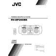
RV-DP200BK
<CD Unit >
Prior to performing the following procedure, remove the front cabinet, the rear cabinet and the CD unit.
CN419 CN418 Main Switch board CN410 CN417
Removing the main switch board and illumination boad. (See Fig.22)
1. Disconnect the card wire from connector CN411 and CN412, and the harness from CN401,CN419 and CN410 of the main switch board on the underside of the CD unit. 2. Remove the four screws R attaching the main switch board and illumination board.
R
CN413
R
CN411 CN412
CN415
R
Illumination board
R
CD unit Fig.22
CN401
Removing the micon board
(See Fig.23)
Prior to performing the following procedure, remove the main switch board. CAUTION: Prior to disconnecting the card wire from connector CN601 on the micom board, solder the short-circuit land on the pickup unit. Disconnecting the card wire extending from the pickup unit may cause damage to the pickup unit. When reassembling, unsolder the short-circuit land on the pickup unit after connecting the card wire to connector CN601. Fig.25 shows more detail about the short-circuit land.
CN602
S
CN601
S
CN412
(Disconnect after soldering the short-circuit land.)
d
CN911 CN916 CN422
S
S
Micom board
CN912
Fig.23
1. Disconnect the card wires from connector CN601 and CN911 on the micon board. 2. Remove the spacer fixing the harnesses marked d. 3. Remove the four screws S attaching the micon board. 4. Disconnect the harness from connector CN912 and CN602 on under side of the micon board respectively.
1-11
|
|
|
> |
|