|
|
|
Categories
|
|
Information
|
|
Featured Product
|
|
|
 |
|
|
There are currently no product reviews.
 ;
A good manual. Had everything i needed to make the repair.
;
This manual is a complete guide, including later additions. It has all the necessary information about the replacement items. The material quality is great to read.
 ;
This manual is very helpful, correct shematic diagram, and good exploded view.Perfect!
;
Alte gescannte Servicepläne sind oft doch etwas undeutlich . Stromlaufpläne werden auf mehrere DIN A4 Seiten aufgeteilt. Alles ziemlich umständlich und zeitaufwendig. Aber mit etwas Mühe geht alles.
;
Great item, high resolution, detailed, very easy to work with.
RX-5020VBK/RX5022VSL
Disassembly method
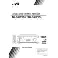
Removing the top cover (See Fig.1)
1. Remove the four screws A attaching the top cover on both sides of the body. 2. Remove the three screws B on the back of the body. 3. Remove the top cover from behind in the direction of the arrow while pulling both sides outward.
Top cover
B
A
2
A
2
Fig.1
Front panel assembly
Removing the front panel assembly (See Fig.2 and 3)
Prior to performing the following procedure, remove the top cover. 1. Disconnect the card wire from connector CN402 on the audio board and CN201 on the power supply board in the front panel assembly. 2. Cut off the tie band fixing the harness. 3. Remove the three screws C panel assembly. attaching the front
C
Tie band
C
CN201
Main board CN402 Power supply board
Audio board
Fig.2
Front panel assembly
4. Remove the four screws D attaching the front panel assembly on the bottom of the body. Detach the front panel assembly toward the front.
D
D
Removing the rear panel
(See Fig.4)
Prior to performing the following procedure, remove the top cover. 1. Remove the power cord stopper from the rear panel by moving it in the direction of the arrow. 2. Remove the seventeen screws E attaching the audio input board, DVD board, video board and tuner board to the rear panel on the back of the body. 3. Remove the four screws F attaching the rear panel on the back of the body. Fig.3
EEEE E
E
Cord stopper
F F
Rear panel
F
EF
Fig.4
1-4
|
|
|
> |
|