|
|
|
Categories
|
|
Information
|
|
Featured Product
|
|
|
 |
|
|
There are currently no product reviews.
 ;
A great copy of the manual, and the only one I could find anywhere on the net! The circuit diagrams are easily readable, all component values marked and easy to see. A highly appreciated download!
 ;
Great Manual. This manual is available no where else. It was exactly what I was looking for.
;
The TEAC A-1500's Service Manual was instrumental in reviving this classic reel-to-reel. Not only does it have the schematics, exploded parts diagram and parts list, it also provided mechanical adjustment information that approximate factory default settings.
;
This service manual was determinant to enable to fix my Alpine Amplifier. I am pleased with my purchase. For a 5 star rating I would like to see a higher resolution scan of the printed circuit board lay-out because the gray scale grafics was dificult to see. Also some schematic diagrams were scanned at a slight angle. Never the less, it had all information I needed to troubleshoot and service my equipment.
;
Complete manual, the good quality of reproduction allows enlarged print-out of the schematic diagram in the size it probably had in the original print edition and which is necessary for practical use.
RX-5032VSL
2.7 Removing the speaker terminal board (See Fig.8) � Prior to performing the following procedure, remove the top cover and rear panel. (1) From the top side of the main body, remove the solders from the soldered sections a on the speaker terminal board.
Parallel wires
Soldered sections a Speaker terminal board Fig.8
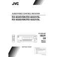
2.8 Removing the main board (See Fig.9) � Prior to performing the following procedure, remove the top cover. (1) From the top side of the main body, remove the tie bands fixing the wires. (2) Remove the tie band and wire protection board fixing the card wire. (3) Remove the solders from the soldered section b on the (4) (5) (6) (7) (8) (9) speaker terminal board attaching the parallel wires. Disconnect the relay board from the connectors (CN291, CN491) on the power supply board and audio board. Disconnect the parallel wire from the connector CN241 on the power supply board. Disconnect the wire from the connector CN251 on the power transformer board 1. Disconnect the wires from the connectors CN471, CN472 and CN473 on the audio board. Remove the screw H, two screws J and four screws K attaching the main board. Take out the main board.
Relay board Tie bands K Main board K Tie band Tie band Wire protection board CN251 CN291 Power transformer board 1 Power supply board CN241
K
J
Card wire CN473
Power transformer
H
CN472 Audio Parallel wires board CN471 CN491 Speaker terminal board Soldered section b
Fig.9
(No.22028)1-7
|
|
|
> |
|