|
|
|
Categories
|
|
Information
|
|
Featured Product
|
|
|
 |
|
|
There are currently no product reviews.
 ;
This schema available for me in good condition. I would highly recommend.
;
Thanks for this "hard to find" service manual.
I apreciate the good quality of scanning and the pages scanned in A3 format.
;
Helpd me mont a new carradio when prewius mont was a mess.
;
Very good service and quick service, very good quality of service manual!
;
Great tape deck manual!
I'm very positively surprised, because it is a very long manual, lot of pages, drawings, diagrams, description of how to make the alignment and adjustment procedures.
It is as good as the old "Naka" manuals from the 1970's - if somebody have seen them, they know what I mean by that.
I recommend to buy this very much !
RX-6010VBK/6018VBK
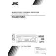
Disassembly method
Removing the top cover (See Fig.1)
1. Remove the four screws A attaching the top cover on both sides of the body. 2. Remove the three screws B on the back of the body. 3. Remove the top cover from behind in the direction of the arrow while pulling both sides outward.
Top cover
B
A
2
A
2
Fig.1
Front panel assembly
C
Removing the front panel assembly (See Fig.2 and 3)
Prior to performing the following procedure, remove the top cover. 1. Disconnect the card wire from connector CN402 on the audio board and CN201 on the power supply board in the front panel assembly. 2. Cut off the tie band fixing the harness. 3. Remove the three screws C attaching the front panel assembly. 4. Remove the four screws D attaching the front panel assembly on the bottom of the body. Detach the front panel assembly toward the front.
Audio board Tie band
C
CN201
Main board CN402 Power supply board
Fig.2
Front panel assembly
D
D
Removing the rear panel (See Fig.4)
Prior to performing the following procedure, remove the top cover. 1. Remove the power cord stopper from the rear panel by moving it in the direction of the arrow. 2. Remove the seventeen screws E attaching the each boards to the rear panel on the back of the body. 3. Remove the four screws F attaching the rear panel on the back of the body. Fig.3
EEEE E
E
Cord stopper
F F
Rear panel
F
E
F
Fig.4
1-4
|
|
|
> |
|