|
|
|
Categories
|
|
Information
|
|
Featured Product
|
|
|
 |
|
|
There are currently no product reviews.
 ;
The product was good and just what I needed, however I had moderate difficulty with the down load because the sight would not recognize my pass word. I was finally given a direct link to the manual and that worked.
 ;
Very quick and easy website to use and fast download of manual, quality of manual is excellent and will be pleased to use this service again in the future, thanks so much!
;
It is an very good and clear scanned service manual.
very recommended.
;
Easy to order the manual. Good quality and fast delivery.
;
The Service Manual for Sansui AU-9500 was very helpfull, in complete and in good printable condition.
Thanks.
RX-6000VBK/RX-6008VBK/RX-6100VBK
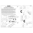
Removing the regulator board / the rear -Rch amplifier board (See Fig.10 and 11)
Prior to performing the following procedure, remove the top cover. 1. Disconnect the harness from connector CN831 on Volume control the main board. board
CN512 Main board CN511 Regulator board Tie band Tie band
Main board CN831
Tie band
2. Remove the two screws H attaching the regulator board to the heat sink. 3. Disconnect the harness from connector CN511 on the main board and CN512 on the volume control board. Cut off the three tie bands fixing the harnesses. 4. Remove the two screws I attaching the rear-Rch amplifier board to the heat sink.
Rear-Rch amplifier board
Fig.10
Regulator board Rear-Rch amplifier board
H
I
Removing the main board (See Fig.12 and 13)
Prior to performing the following procedure, remove the top cover, the rear panel, the relay board and the preamplifier board. 1. Disconnect the card wire from connector CN811 on the main board. 2. Unsolder each harness connecting the power transformer and the main board. 3. Unsolder the power cord on the main board. 4. Remove the eight screws J board to the heat sink. 5. Remove the eight screws K board. attaching the main
Heat sink
Fig.11
K
Main board CN811 Speaker switch board
K
Soldered part
FW902 Power transformer
K
Main board
K J
Soldered part
Fig.12
J
Heat sink
attaching the main
6. For the harness extending from the speaker switch board, unsolder FW902 on the main board.
Power transformer
Main board CN811
Fig.13
2-4
|
|
|
> |
|