|
|
|
Categories
|
|
Information
|
|
Featured Product
|
|
|
 |
|
|
There are currently no product reviews.
 ;
Very quick and easy website to use and fast download of manual, quality of manual is excellent and will be pleased to use this service again in the future, thanks so much!
;
It is an very good and clear scanned service manual.
very recommended.
;
Easy to order the manual. Good quality and fast delivery.
;
The Service Manual for Sansui AU-9500 was very helpfull, in complete and in good printable condition.
Thanks.
;
Dear Sir,
Document is original service document of sharp. I had a problem with the door contacts. Fuses where blown. With the manual in a few minuts is was clear what the problem was.
Manual was of great help.
With kind regards,
Martie Verhoeven
The Netherlands.
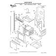
RX-7001PGD Removing the power supply board (See Fig.18 and 19)
Prior to performing the following procedure, remove the top cover and the front panel. 1. Remove the one nut attaching the headphone jack of the power supply board on the front side of the body. 2. Disconnect the relay board 1, 2 and 3 from the power supply board and the main board respectively. 3. Disconnect the harness connected to connector CN55 and CN56 on the power transformer board (If necessary, cut off the band fixing the harness on the side of the base chassis). 4. Remove the four screws O attaching the power supply board and pull out the power supply board from the front bracket backward. 5. Unsolder the three harnesses connected to the Relay board 2 power supply board.
Power supply board Nut Headphone jack
Fig.18
Power supply board Headphone jack Relay board 1
O
Solder
O
Solder
O
Tie band CN55 CN56 Tie band
Removing the system control board / power switch board (See Fig.20 to 21)
Prior to performing the following procedure, remove the top cover and the front panel assembly. 1. Pull out the volume knob on the front side of the front panel and remove the nut attaching the system control board. 2. Remove the six screws P attaching the system control board on the back of the front panel and disconnect the harness from connector CN422 on the system control board. 3. Disconnect the harness from connector CN430 on the power switch board.
Relay board 3
Power transformer
Fig.19
Nut Front panel
Volume knob
4. Remove the five screws Q switch board.
attaching the power
System control board
Fig.20
Power switch board
P
Q Q
P
CN422 Front panel assembly
CN430
P
Fig.21
1-7
|
|
|
> |
|