|
|
|
Categories
|
|
Information
|
|
Featured Product
|
|
|
 |
|
|
There are currently no product reviews.
 ;
Bon produit. Permet de corriger les couleurs et de redonnez un petit coup de jeune à vos vieilles vidéos. On regrettera juste le manque d'une prise s-vidéo.
 ;
Quality scan of the actual service manual, just what I was looking for.
;
Straightforward ordering process. Service manual scan was clear & easy to read. Very comprehensive instructions for alignment. Excellent, thank you.
;
Fast, clear and useful. Important for me: the manual is in German.
;
Very good quality. Some parts are not fully readable, but the fundamental ones are fine.
RX-7022RSL/RX-7020RBK
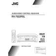
Removing the audio board (See Fig.10)
Relay board power supply board CN291 Power transformer Power / Fuse board
Prior to performing the following procedure, remove the top cover and the rear panel. 1. Disconnect the card wire from connector CN402 CN403 on the audio board. 2. Disconnect the relay board from the audio board and the power supply board. (CN291, CN491) 3. Disconnect the harness from connector CN471, CN472, CN473. 4. Remove the three screws G board assembly. 5. Remove the screw H assembly. attaching the audio
CN403 CN473
G
CN402
G
Audio board CN472 CN471
G CN491 H
Fig.10
attaching the audio board
I
(See Fig.11)
CN241
Removing the main board
Prior to performing the following procedure, remove the top cover, the rear panel and audio board. 1. Disconnect the harness from connector CN241 and CN203 on the power supply board respectively. 2. Disconnect the harness from connector CN251 on the power transformer board . 3. Remove the four screws I and the two screws J attaching the main board.
I J I
Main board
J
CN251
CN203
I
Fig.11
Removing the heat sink (See Fig.12 to 14)
Prior to performing the following procedure, remove the top cover and main board. 1. Remove the two screws K attaching the heat sink to the reverse side of main board. 2. Disconnect the for connectors with each amp. board, and remove the main board.
K
K
Fig.12
Main board rear side
Front Rch amp. board Heat sink Front Lch amp. board Center amp. board
3. Remove the four screws M and ten screws L Rear Lch amp. board attaching the heat sink. Rear Rch amp. board
Heat sink
L
L
L M
Main board
M
CN802 CN801 CN302 CN301
CN901
Fig.14
Fig.13
1-5
|
|
|
> |
|