|
|
|
Categories
|
|
Information
|
|
Featured Product
|
|
|
 |
|
|
There are currently no product reviews.
 ;
thanks you are the best.Very good detail, Quick service response. A useful service manual with all details.
;
Great service!!! Polecam gorąco wszystkim zainteresowanym
;
I liked the price plus it had everything i needed to service the tv.
thankyou Tim Hertz
;
The manual is excellent, well detailed, and divided into two parts. Received very quickly. Thank you.
;
a solid deal - quick and without any problems.
I life in europe - with downloads no loosing time
once again
RX-7022VSL
Disassembly method
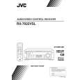
Removing the top cover (See Fig.1)
1. Remove the four screws A attaching the top cover on both sides of the body. 2. Remove the three screws B on the back of the body. 3. Remove the top cover from behind in the direction of the arrow while pulling both sides outward.
Top cover
B
A
2
Fig.1
A
2 Front panel assembly
C
Removing the front panel assembly (See Fig.2 and 3)
Prior to performing the following procedure, remove the top cover. 1. Disconnect the card wire from connector CN402 on the audio board and CN201 on the power supply board in the front panel assembly. 2. Cut off the tie band fixing the harness. 3. Remove the three screws C attaching the front panel assembly. 4. Remove the four screws D attaching the front panel assembly on the bottom of the body. Detach the front panel assembly toward the front.
Audio board Tie band
C
CN201
Main board CN402 Power supply board
Fig.2
Front panel assembly
D
D
Removing the rear panel (See Fig.4)
Prior to performing the following procedure, remove the top cover. 1. Remove the power cord stopper from the rear panel by moving it in the direction of the arrow. 2. Remove the thirty-four screws E attaching the each boards to the rear panel on the back of the body. 3. Remove the four screws F attaching the rear panel on the back of the body. Fig.3
EEE E
E
EE
Cord stopper
E
F
Rear panel
F
E
F
Fig.4
1-3
|
|
|
> |
|