|
|
|
Categories
|
|
Information
|
|
Featured Product
|
|
|
 |
|
|
There are currently no product reviews.
 ;
I'd been looking for this manual for awhile. Exactly what I needed - and at an excellant price. Thanks!
;
very complete. acceptable resolution. details are a little unclear. is a manual note 8.
;
excellent service - fast purchase - easy download - will buy from again
 ;
Manual is actually a pack of schematics, good quality pictures.
;
Great service. Manual delivered at a great price. Reliable delivery service. They have a great selection. A recommended service!
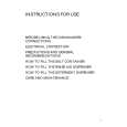
RX-8012VSL/RX-8010VBK Removing the power transformer (See Fig.18)
Prior to performing the following procedures, remove Power the top cover. transformer
board Power supply board
1. Unsolder the two harnesses connected to the power transformer. 2. Disconnect the harness from connector CN55 and CN56 on the power transformer board. CN55 / 56
M
3. Remove the four screws M attaching the power transformer.
Power transformer
Removing the power / fuse board (See Fig.18)
Prior to performing the following procedure, remove the top cover and the rear panel. 1. Remove the screw N attaching the power / fuse board. 2. Unsolder the power cord and other harnesses connected to the power / fuse board.
Solder points Power cord
M N
Solder points Power / fuse board
Fig.18
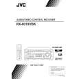
Removing the power supply board (See Fig.19 to 21)
Prior to performing the following procedure, remove the top cover and the front panel. 1. Remove the screw O fixing a bonding ground. 2. Remove the one nut attaching the headphone jack of the power supply board on the front side of the body. 3. Remove the front panel assembly. and the screw a ground. 4. Disconnect the card wire from connector CN402 on the power supply board. 5. Remove the three screws P attaching the power supply board and pull out the power supply board from the front bracket backward. 6. Unsolder the three harnesses connected to the power supply board.
Power supply board
O
Nut
Headphone jack
Fig.19
Headphone jack
Power supply board
P
CN402
P
Hook
Tie band
P
Tie band Solder
Fig.20
1-7
|
|
|
> |
|