|
|
|
Categories
|
|
Information
|
|
Featured Product
|
|
|
 |
|
|
There are currently no product reviews.
 ;
Fint forløb med levering af manualen. Kvaliteten af skanningen betegnes som middel
 ;
I found the manual to be clear concise and complete. It was of immense assistance when removing the unit as the unit was over 22 years old and the wiring diagram was unobtainable from the manufacturer. The exploded drawings were clear as were the instructions and labels.
;
I will highly recommend this seller. They are honest, accurate, fast and responsible.
;
This manual was very good & was very helpful with repairs.
Always great & fast service from Owner's manual.
;
Very pleased with the quality of the scan. No complaints whatsoever.
RX-8022PSL
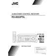
Removing the main board (See Fig.13 to 15)
Prior to performing the following procedure, remove the top cover.
Tie band
M
CN721 CN723
Tie band
M
1. Remove the card wire and cut off the tie bands.
Card wire
2. Disconnect the harness from the connector CN721, L CN723, CN813, CN814, CN831 and CN881 on the main board. Main board 3. Disconnect the harness from the connector CN722 on the Cch amp. board (see fig.5). 4. Disconnect the harness from the connector CN811 on the power trans1 board. 6. Remove the screw K, after removing the relay board if needed (see fig.11). 7. Remove the two screws L and the six screws M attaching the main board. 8. Remove the two screws N attaching the heat sink to the main board. 9. Disconnect the connector of each amp. board.
CN831 CN814 CN813
CN811 Power trans1 board CN722
K
L
CN881
Fig.13
Heat sink
N
Main board (reverse side)
Fig.14
Rch amp. board Lch amp. board Cch amp. board
Removing the each amp. board of Cch, Lch, Rch, RLch and RRch (See Fig.16)
Prior to performing the following procedure, remove the top cover and main board.
RLch amp. board RRch amp. board
Heat sink
Main board
1. Remove the two screws O attaching the Cch amp. board and remove the Cch amp. board. 2. Remove the two screws P attaching the Lch amp. board and remove the Lch amp. board. 3. Remove the two screws Q attaching the Rch amp. board and remove the Rch amp. board. 4. Remove the two screws R attaching the RLch amp. board and remove the SLch amp. board. 5. Remove the two screws S attaching the RRch amp. board and remove the SRch amp. board.
CN706 CN705 CN702 CN701 CN703
Fig.15
S(RRch)
Q(Rch)
Heat sink
O(Cch)
Removing the Heat sink
(See Fig.16)
T
T
Prior to performing the following procedure, remove the top cover, main board and each amp. board. 1. Remove the four screws T attaching the two brackets to the heat sink and remove the two brackets. 1-6
Bracket
R(RLch)
Fig.16
P(Lch)
Bracket
|
|
|
> |
|