|
|
|
Categories
|
|
Information
|
|
Featured Product
|
|
|
 |
|
|
There are currently no product reviews.
 ;
This is an excellent information source. Great quality and tons of info regarding technical service for the Technics SH8065.
;
5 stars on this manual since it is the complete version, not the half manual you find free for download all over the web. Good job.
;
Thank you very much you are helping me a lot with my preferred hobby!!! this manual of an old TV is going to be very helpful!!!!
You are very honest competent great job very clear and well done!!!!
Matteo
;
An excellent service manual contains dismantling locations of components, electronic adjustments,worth the money.
;
Caracteristiques,circuit adjusment,notes on schematis diagram,it's a good service manual,to live well,thanks.
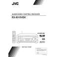
RX-9010VBK
Removing the system control board / power switch board (See Fig.21 to 23)
Prior to performing the following procedure, remove the top cover and the front panel assembly. 1. Pull out the volume knob on the front side of the front panel and remove the nut attaching the system control board. 2. Remove the two screws P switch board. 3. Remove the two screws Q board. attaching the power
Volume knob Power switch board Operation switch panel Nut Front panel assembly
attaching the switch
Switch board
Fig.21
4. Remove the cords from the three hooks a. 5. Remove the eight screws R attaching the system control board on the back of the front panel. 6. On the back of the front panel, release the four joints by pushing the joint tabs inward. Remove the operation switch panel toward the front.
R
R
Cords
R
Q P
Joint Joint Joint Joint Hook a
7. Disconnect the harness from connector CN420 and CN422 on the system control board. 8. Release the two hooks b attaching the system control board.
Fig.22
System control board
CN420
Hook b
Hook b
CN422
Fig.23
System control board reverse side
Matters that require attention during replacement of IC400 (See Fig.24 to 25)
In case where there is a resistance array: Both onetime IC and mask IC can be used In case where there is no resistance array: Only mask IC can be used
IC400
Fig.24
System control board top view
Resistance array
Fig.25
1-9
|
|
|
> |
|