|
|
|
Categories
|
|
Information
|
|
Featured Product
|
|
|
 |
|
|
There are currently no product reviews.
 ;
I AM HIGHLY IMPRESSED BY THE EASE OF USE OF THIS DOWNLOAD SERVICE. INSTRUCTIONS ARE CLEAR AND SIMPLE TO FOLLOW....EVEN BY TECHNOPHOBES SUCH AS MYSELF. THE EMAILS POINT YOU IN THE RIGHT DIRECTION...ITS SO EASY PEASY. THE DOWNLOAD CHOICE OF USER MANUALS IS EXTENSIVE AND I COULD NOT FIND A CHEAPER OR MORE EFFICIENT SERVICE ON THE INTERNET. I COULD NOT HAVE MADE A BETTER CHOICE OF INFORMATION PROVIDER. SHOULD I EVER NEED ANOTHER USER MANUAL, THEN THIS IS THE FIRST CHOICE SITE. COULD NOT BE BETTER PLEASED!!!!!!!...MANY THANXES FROM JIM BURNS
;
I was impressed with the quality of service (frequent e-mails to let you know the status of your order), and the speed at which the download became available. The manual was a life saver and was not easy to track down. Thank you for such an excellent service.
;
the manual was just what i wanted it had all the revelent information required to operate the hifi .Iwould use any manual i downloaded for any item which needs a manual
;
Die gewünschte Bedienungsanleitung wurde vereinbarungsgemäß in deutsch bereitgestellt. Sie ist gut lesbar. Kein Kauderwelsch.
Danke für den Service.
;
GOOD SERVICE MANUAL GOT ALL THE INFO. THAT I NEEDED..
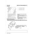
Setting Up the RF Rod Antenna
The remote control supplied for this receiver can transmit RF (Radio Frequency) signal. The RF rod antenna can receive the RF signals emitted from the remote control. So, with the RF rod antenna connected, you can operate the receiver at a distance of up to 50 feet (15 m) using the remote control. However, if the antenna cannot receive signals stably, you cannot operate the receiver correctly. � The signal-reachable distance may differ depending on the operating conditions and circumstances. To improve transmitting conditions, change the distance to the receiver and the direction to transmit while operating the remote control. � Without the RF rod antenna connected, you can operate the receiver with the remote control, aiming the remote control directly toward the remote sensor on the receiver.
Setting Up the IR Signal Transmitter
The IR signal transmitter can transmit the IR signals. It allows you to use the AV COMPULINK system, and to operate other manufacturers� components without aiming the remote control directly toward the remote sensor on the target components. In addition, the IR signal transmitter reduces the possibility of malfunction. � The IR signal transmitter may not operate the target components depending on the operating conditions and circumstances � including the aiming angle and direction of the IR signal transmitter toward the remote sensors of the target components. If this occurs, changing its aiming angle and direction toward the remote sensors may solve the problem.
To set up the IR signal transmitter To set up the RF rod antenna
1. Find the place where you attach the IR signal transmitter.
� Place it where the signal can reach the remote sensor of the target components directly (in the line-of-sight). � If the cord length of the IR signal transmitter is not long enough, use an extension cord (not supplied).
1. Insert the RF rod antenna to the RF REMOTE ANTENNA terminal.
RF REM
IR OU T
O
TE
NN
AN
TE
2. Attach the double-sided adhesive tape (supplied) to the IR signal transmitter.
A
IR signal transmitter
2. Rotate the fixing nut to attach the RF rod antenna firmly.
RF REM
IR OU T
O
T
Double-sided adhesive tape
E
NA
h t s s e L
AN
TE N
3. Connect the plug of the transmitter to the IR
( n a
OUT jack of the receiver and place the transmitter.
RF REMOTE ANTENNA IR OUT
0 m f )
The RF rod antenna and IR signal Transmitter
The combination of the RF rod antenna and the IR signal transmitter (see to the right) allows you to use the Multi-room function more conveniently. The remote control supplied for this receiver can transmit both RF (Radio Frequency) signal and IR (infrared) signal at the same time. This receiver catches the RF signals emitted from the remote control, and converts them into IR signals, then transmits the converted signals to the remote sensor on the other components through IR signal transmitter. This means that you can control not only this receiver but the other components from the sub-room.
ee t 31
At an angle of approx. 60°
Signal-emitting angle of the transmitter Horizontally: 60� Vertically: 60�
15° 45°
Note:
To avoid a failure in the reception from the remote control, keep the connecting cables and the IR signal transmitter� s cable away from the RF rod antenna.
30° 30°
12
|
|
|
> |
|