|
|
|
Categories
|
|
Information
|
|
Featured Product
|
|
|
 |
|
|
There are currently no product reviews.
 ;
Ckear manual, well reproduced with plenty of overlap on critical pages.
;
I buy the service manual cheaper here than in elsewhere.Am happy with this site. I recommended the Owner-Manuals.com
;
Great Manual. It was exactly what I was looking for
;
Great Manual. It was exactly what I was looking for
;
I am really satisfied. It was ceap, easy and quick. Te owner manual is a full service book. I got what I expected. Thx
3.1.17 Removing the DSP connect board (See Fig.14) � Remove the top cover, rear panel, tuner, compulink board and DSP board. Disconnect the DSP connect board from the input board in an upward direction while releasing the claw k of the connector CN502 on the input board. Note: When releasing the claw k, take care not to break it. 3.1.18 Removing the input board (See Fig.14) � Remove the top cover, rear panel, tuner, compulink board, DSP board and DSP connect board. (1) Remove the tie bands bundling the wires. Reference: After reassembling, bundle the wires with the new tie bands as before. Disconnect the wire from the connector CN209 on the speaker terminal 2 board. Disconnect the wire from the connector CN513 on the OSD connect 1 board. Disconnect the wires from the connectors (CN530, CN531, CN552) on the input board. Disconnect the parallel wire from the connector CN540 on
CN530 CN540 Tie band OSD connect 1 board Tie band CN531 CN513 CN552
T T
Input board DSP connect board k Input board
(2) (3) (4) (5)
T
CN209
Speaker terminal 2 board
the input board. (6) Remove the three screws T and take out the input board from the main body.
CN502
Fig.14 3.1.19 Removing the OSD connect 1 board (See Fig.15) � Remove the top cover and DSP board. (1) Remove the tie band bundling the wires. (2) Disconnect the wire from the connector CN524 on the subwoofer board. (3) Disconnect the wire from the connector CN513 on the OSD connect 1 board. (4) Disconnect the OSD connect 1 board from the main amplifier board in an upward direction while releasing the claw m of the connector CN222 on the main amplifier board. Note: When releasing the claw m, take care not to break it.
OSC connect 1 board m
CN222 OSC connect 1 board Main amplifier board
Tie band CN513
CN524 Subwoofer board
Fig.15
1-14 (No.MB364)
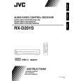 $4.99 RX-D201S JVC
Owner's Manual Complete owner's manual in digital format. The manual will be available for download as PDF file aft…
|
|
|
> |
|