|
|
|
Categories
|
|
Information
|
|
Featured Product
|
|
|
 |
|
|
There are currently no product reviews.
 ;
I had been looking everywhere for a proper service manual for this VCR. Everywhere else that has this available for download has a very light version. This is the full service manual with all aspects that would interest anyone looking for the service manual for the AIWA HV-MX100 Worldwide VHS VCR. Great quality (as always). A winner hands down. Best Quality.
;
Top quality manual. Covers all aspects you'd expect in a top quality service manual for this Panasonic VHS VCR. The manual resolution is high. Another top quality manual from the only site worth downloading manuals from! If you're looking for a manual for the PV-9662 VHS VCR, this is the one you'll want to get!
;
complete part-lists and pcb layout, schematic diagram is good enlargable,
;
Excellent, fast delivery, excellent product. Good luck!
;
This manual is for the usa model only. But it is clear
, accurate and comprehensive, including board layouts and schematics.
I found it extremely useful for my mitsubishi dp-86da, but the same diagram would also work for the realistic lab5000 and hi fi 80. Thanks.
3.1.17 Removing the DSP connect board (See Fig.14) � Remove the top cover, rear panel, tuner, compulink board and DSP board. Disconnect the DSP connect board from the input board in an upward direction while releasing the claw k of the connector CN502 on the input board. Note: When releasing the claw k, take care not to break it. 3.1.18 Removing the input board (See Fig.14) � Remove the top cover, rear panel, tuner, compulink board, DSP board and DSP connect board. (1) Remove the tie bands bundling the wires. Reference: After reassembling, bundle the wires with the new tie bands as before. Disconnect the wire from the connector CN209 on the speaker terminal 2 board. Disconnect the wire from the connector CN513 on the OSD connect 1 board. Disconnect the wires from the connectors (CN530, CN531, CN552) on the input board. Disconnect the parallel wire from the connector CN540 on
CN530 CN540 Tie band OSD connect 1 board Tie band CN531 CN513 CN552
T T
Input board DSP connect board k Input board
(2) (3) (4) (5)
T
CN209
Speaker terminal 2 board
the input board. (6) Remove the three screws T and take out the input board from the main body.
CN502
Fig.14 3.1.19 Removing the OSD connect 1 board (See Fig.15) � Remove the top cover and DSP board. (1) Remove the tie band bundling the wires. (2) Disconnect the wire from the connector CN524 on the subwoofer board. (3) Disconnect the wire from the connector CN513 on the OSD connect 1 board. (4) Disconnect the OSD connect 1 board from the main amplifier board in an upward direction while releasing the claw m of the connector CN222 on the main amplifier board. Note: When releasing the claw m, take care not to break it.
OSC connect 1 board m
CN222 OSC connect 1 board Main amplifier board
Tie band CN513
CN524 Subwoofer board
Fig.15
1-14 (No.MB364)
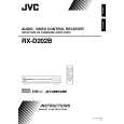 $4.99 RX-D202B JVC
Owner's Manual Complete owner's manual in digital format. The manual will be available for download as PDF file aft…
|
|
|
> |
|