|
|
|
Categories
|
|
Information
|
|
Featured Product
|
|
|
 |
|
|
There are currently no product reviews.
 ;
Service manual in good quality, it was very helpful to me. Perfect service, I am very satisfied.
Jochen Kelm
;
Exellent manual ,it was in great condition,and got all the info i expected,5 stars!!
;
I searched the Internet exhaustively for this manual and Owner-Manuals was the least expensive...but provided an excellent reproduction within 4 hours. Very satisified.
 ;
Rapid and precise delivery. Good print. On the spot.
;
available for me the service manual is in order!
thanks
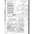
RX-DP10VBK/RX-DP10VSL RX-DP10RSL
<Front panel assembly section>
Removing the FL display board & front AV in board (See Fig.1 and 2)
Prior to performing the following procedure, remove the top cover and the front panel assembly. 1. Pull out the volume knob on the front side of the front panel assembly and remove the nut attaching the FL display board. 2. Disconnect the harness from the connector CN973 on the front AV in board. 3. Remove the three screws A attaching the front AV in board. 4. Remove the nine screws B attaching the FL display board on the back of the front panel. 5. Disconnect the harnesses from connector CN969, CN975 and CN982 on the FL display board.
Operation switch panel
Nut Front panel assembly
Door Volume knob
Fig.1
Front AV in board FL display board CN969
CN975
Removing the power switch board & motor assembly (See Fig.3)
Prior to performing the following procedure, remove the front panel assembly and the FL display board. 1. Remove the four screws C attaching the power switch board. 2. Remove the three screws D attaching the motor assembly on the back of the front panel. 3. Remove the belt and the two screws a attaching the motor.
CN973
A
B
CN982
B C
Fig.2
Power switch board
E
Door
E
Belt
D
Removing the door input board (See Fig.3 and 4)
Prior to performing the following procedure, remove the front panel assembly and the FL display board. 1. Remove the four screws E attaching the door and remove the door from front panel assembly. Remove the six screws F attaching the door input 2. board. Fig.3
Motor assembly a
F
Door input board Door
Fig.4
1-13
|
|
|
> |
|