|
|
|
Categories
|
|
Information
|
|
Featured Product
|
|
|
 |
|
|
There are currently no product reviews.
 ;
We received the manual in a timely manner and it was exactly what we were expecting. Excellent replacement for original Service Manual.
All schematics are very legible. We are really satisfied.
;
We received the manual in a timely manner and it was exactly what we were expecting. Excellent replacement for original Service Manual.
All schematics are very legible. We are really satisfied.
;
We received the manual in a timely manner and it was exactly what we were expecting. Excellent replacement for original Service Manual.
All schematics are very legible. We are really satisfied.
;
We received the manual in a timely manner and it was exactly what we were expecting. Excellent replacement for original Service Manual.
All schematics are very legible. We are really satisfied.
;
Fast delivery and good quality manual.
Very easily downloadable from a given url.
Will be pleased to buy again from this seller.
RX-DV5RSL
Disassembly method
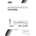
Removing the top cover (See Fig.1)
1. Remove the four screws marked A attaching the top cover on both sides of the body. 2. Remove the three screws marked B on the back of the body. 3. Remove the top cover from behind in the direction of the arrow while pulling both sides outward.
Top cover
B
A
2
A
2
Fig.1
Tie band
Front panel assembly CN114
Removing the front panel assembly (See Fig.2 to 4)
Prior to performing the following procedures, remove the top cover. 1. Disconnect the card wire from the connector CN114 on the main board. 2. Remove the screw marked C attaching the earth wire to the power supply board. 3. Remove the five screws marked D attaching the front panel assembly on the bottom of the body. Detach the front panel assembly toward the front. 4. Release the two joints marked a on both sides of the body using a screwdriver.
C
Power supply board
Main board Amplifier board
CN201 DSP board
Power /Fuse board
Fig.2
Front panel assembly
D
D
Joint a
Fig.4
Fig.3
Removing the rear panel
(See Fig.5)
Cord stopper Rear panel
Prior to performing the following procedures, remove the top cover. 1. Remove the power cord stopper from the rear panel by moving it in the direction of the arrow. 2. Remove the eighteen screws marked E attaching each boards to the rear panel on the back of the body. 3. Remove the fore screws marked F attaching the rear panel on the back of the body.
E
E
F
F
EF
Fig.5
E
F
1-5
|
|
|
> |
|