|
There are currently no product reviews.
 ;
I must admit, I was very skeptical... $4.99 for a 74 page service manual. I've seen some very poorly scanned manuals on the Internet, but this one is VERY good quality! Even when zooming into 500%. Great Deal!
;
Very good detail, Quick service response. A useful service manual with all details. I recomend this service.
;
As Always you can find here manuals even of difficult TV scheme which are scan in almost perfect way.clear and fast!!!!!
Great work thanks!
;
Incredibly clear!!!! Well done, complete and wonderful. It could not better than this!!!!
 ;
Thank You for fast delivery for the sheme.
Everything allright.
Thanks & best regards Franz
RX-DV5SL
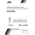
Removing the amplifier board (See Fig.11, 12)
Prior to performing the following procedures, remove the top cover and rear panel. 1. Disconnect the wire from the connector CN201 on the amplifier board. 2. Disconnect the amplifier board from the connector CN212 on the main board. 3. Disconnect the amplifier board from the wire connected to the connector CN231 and CN241 on the main board on the fan bracket. 4. Disconnect the screws marked G attaching the earth wire and the amplifier board. 5. Disconnect the four screws H attaching the amplifier board on the body. Fig.11
Tie band CN201
G H
CN212 DSP board
CN231 CN241 Amplifier board
CN212 CN231 CN241 Main board
Fig.12
Removing the power ICs (See Fig.13, 14)
Prior to performing the following procedures, remove the top cover, the rear panel and amplifier board. 1. Remove the six screws marked I attaching the power ICs. 2. Unsolder the two power ICs solder points attaching the rear side of the amplifier board. 3. Pull out the amplifier board from the bracket hooks on the heat sink.
Heat sink
Power ICs
I
I
Amplifier board
Fig.13
Power ICs solder points
Fook
Fook
Heat sink Amplifier board rear side
Fig.14
1-7
 $4.99 RX-DV5SL JVC
Owner's Manual Complete owner's manual in digital format. The manual will be available for download as PDF file aft…
|