|
|
|
Categories
|
|
Information
|
|
Featured Product
|
|
|
 |
|
|
There are currently no product reviews.
 ;
The manual was of good quality with high resolution schematic diagrams.
;
The manual was very clear and contained all the information I was looking for. My dishwasher is working again because of this servicemanual!
;
Quality scan, great manual. I solved my problem with this manual.
 ;
The AKAI 1720 model reel to reel tape recorder described in this Manual is quite an old unit - circa late 1960's. As a consequence, the description of the mechanical details - and adjustments thereof - is quite critical. The manual does this quite well. The schematics are also well presented and have detailed PCB overlays. Probably the only negative is that some half-tone detail has been lost from the original manual as it has been scanned in simple B&W.
;
Perfect source for service manuals: fast and professional transaction; high quality, perfect readable and largely scaleable PDF; complete schemes, diagrams and spare part list. Tnx a lot, cu again!!!!
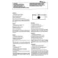
RX-E100RSL/RX-E100RSB Removing the audio board (See Fig.8)
CN515 power supply board Main board CN517 CN516
Prior to performing the following procedure, remove the top cover , the rear panel and the each board. 1. Disconnect the card wire from connector CN411 on the audio board. 2. Disconnect the harness from connector CN205 on the audio board. 3. Disconnect the harness from connector CN515, CN516, and CN517on the main board. 4. Remove the harness band fixing the harness. 5. Remove the three screws G board assembly. attaching the audio
CN411
G
Power transformer
Audio board
Harness band
CN205
Power / Fuse board
Fig.8
H H I I H
Main board
Removing the main board
(See Fig.9)
CN707 CN206
Prior to performing the following procedure, remove the top cover, the rear panel and audio board. 1. Remove the harness band fixing the harness. 2. Disconnect the harness from connector CN707 on the power supply board . 3. Disconnect the harness from connector CN202 and CN206 on the main board . 4. Remove the five screws H and the two screws I attaching the main board.
CN202 Harness band
H
Fig.9
J
Removing the Heat sink (See Fig.10 to 11)
1. Remove the ten screws K and four screws L attaching the heat sink. 2. Remove the two screws J attaching the heat sink from the rear side of main board.
Main board rear side Heat sink
J
Fig.10
K
K
K L
L
Fig.11
1-5
|
|
|
> |
|