|
There are currently no product reviews.
 ;
Correct and accurate service manual for that Siemens (Nordmende) TV. Price is worthwhile as the Manual is fully usable.
 ;
Just what I needed to repair my CT-F600, clear pdf, easy to tread and navigate
;
Yes, cost is low. And quality of some diagrams is low too.
;
Quick response.
Good quality.
Not large price of documents.
Thanks.
Dzięki.
;
All ok:
Good quality.
Quick response.
Not large price of documents.
Thanks
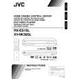
3.1.7 Removing the AC power supply board (See Figs.8 and 9) � Prior to perform the following procedures, remove the top cover and tuner. (1) From the top side of the main body, cut the tie band and disconnect the wires from the connectors CN203 to CN205 and CN218 on the AC power supply board. (2) From the back side of the main body, remove the two screws J attaching the AC power supply board. (See Fig.8) (3) Remove the three screws K attaching the AC power supply board. (4) Remove the fasteners from the reverse side of the AC power supply board. Reference: � After attaching the AC power supply board, bundling the wires using the new tie band.
Rear panel
Strain relief
J
Fig.8
Fastener
K
Wire clamp CN218
Tie band CN203
K CN204
CN205 AC power supply board Power cord Fig.9
3.1.8 Removing the DC power board (See Fig.10) � Prior to perform the following procedures, remove the top cover, front panel assembly and digital input board. (1) From the top side of the main body, disconnect the wires from the connectors (CN201, CN206, CN207, CN211, CN510, CN520, CN711) on the DC power board. (2) Disconnect the parallel wire from the connector CN712 on the amp. board. (3) Disconnect the wire from the connector CN218 on the AC power supply board. (4) Remove the two screws L attaching the DC power board.
CN201 CN520
DC power board CN711 CN206
L
CN510
CN218 CN207 AC power supply board
L
Fig.10
CN211 CN712 Amp. board
(No.MB105)1-7
 $4.99 RX-ES1SL JVC
Owner's Manual Complete owner's manual in digital format. The manual will be available for download as PDF file aft…
|