|
There are currently no product reviews.
 ;
All ok:
Good quality.
Quick response.
Not large price of documents.
Thanks
;
The manual was complete and extremely helpful in both diagnosing the problem I was having as well as fixing it. Excellent quality. I will getting additional manuals in the future.
;
Exactly the JVC service manual and schematics that I was looking for - delivered just hours after order. Will do business again!
;
This is a fantastic site, ad I have been a returning satisfied cusumer!
Thanx for a great sevice!
;
Je suis audiophile belge, électronicien et créateur d'enceintes acoustiques.
J'ai apprécié la qualité des documents fournis. Ils sont très lisibles, ils peuvent être agrandis sans problème et ils sont complets. Pour moi, c'est parfait. Pour cette qualité, je suis d'accord de payer. Et le système de paiement et d'envoi est simple. Merci, continuez comme cela.
Frédéric
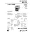
3.1.10 Removing the DC power board (See Fig.14) � Prior to perform the following procedures, remove the top cover, front panel assembly, rear panel and digital input board. (1) From the top side of the main body, disconnect the wires from the connectors (CN201, CN206, CN207, CN211, CN218, CN510, CN520, CN711) on the DC power board. (2) Disconnect the parallel wire from the connector CN712 on the amp. board. (3) Remove the two screws M attaching the DC power board.
CN218 CN520 CN510 CN210
DC power board CN711 CN206
M
CN207
M
Fig.14
CN211
CN712
Amp. board
3.1.11 Removing the main board (See Fig.15) � Prior to perform the following procedures, remove the top cover, front panel assembly, rear panel, digital input board, digital output board, AC power supply board and DC power board. (1) From the top side of the main body, disconnect the wires from the connector CN525 on the main board. (2) Disconnect the wires from the connectors CN516 and CN519 on the amp board. (3) Remove the two screws N attaching the main board. Reference: � When attaching the two screws N, attach the wire holder with it. 3.1.12 Removing the amp. board (See Fig.15) � Prior to perform the following procedures, remove the top cover, front panel assembly, rear panel, digital input board, digital output board, AC power supply board and DC power board. (1) From the top side of the main body, disconnect the wires from the connectors CN516 and CN519 on the amp. board. (2) Disconnect the wire from the connector CN525 on the main board. (3) Disconnect the wire from the connector CN703 on the rectifier board. (4) Remove the four screws P attaching the amp. board.
CN516 Wire holder
Amp. board CN519 Rectifier board CN703
P
P
CN525 Main board
N
Fig.15
P
P
1-10 (No.22070)
|