|
|
|
Categories
|
|
Information
|
|
Featured Product
|
|
|
 |
|
|
There are currently no product reviews.
 ;
Excellent Service manual, good quality scans, quick service and very good value. Well reccomended ! All good.
;
Great value service manual!
Good-quality scans. Detailed and valuable informations.
A+++++++++++++++
;
Great value service manual!
Good-quality scans. Detailed and valuable informations.
A+++++++++++++++
;
Excellent scan quality. A complete and very useful manual with all details.
Great service at low price A+++++++++++++++++
;
The manual is very good quality. very good graphics. complete
1
2
3
4
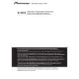
1.3.3 ACOUSTIC ABSORBENTS
When the Network Assy is detached then reattached, removal and placement of the acoustic absorbent is required.
A
Note: Upon reattachment of the Network Assy for the CST unit, before reattaching the enclosure plate, be sure to remove the acoustic absorbent placed at the rear of the chamber. If part of the acoustic absorbent is pinched between the enclosure plate and the plate when the enclosure plate is secured, air leakage may occur and the best performance of the speaker may not be obtained. 1. Acoustic absorbent near the input-terminal plate
1 Remove this acoustic absorbent. When replacing, roll the acoustic absorbent, then push it in under the reinforcing crosspiece. Only this acoustic absorbent needs fixing with adhesive. Therefore, before pushing it in, be sure to apply adhesive to the side panel of the cabinet.
2. Acoustic absorbent within the chamber for the CST unit
1 Remove this piece of acoustic absorbent. When replacing, place it along the interior side of the chamber so that it forms a U shape.
B
C
(Adhesive: DIABOND black/GYL-014)
Fig. 2-5: View after the lower woofer is removed (1)
2 Remove these pieces of acoustic absorbent. When replacing, fold them in two and push them in.
Fig. 2-7: View after the CST unit is removed (1)
2 Remove this piece of acoustic absorbent (near the enclosure plate). When replacing, fold it in two and push it in.
D
Fig. 2-6: View after the lower woofer is removed (2)
Fig. 2-8: View after the CST unit is removed (2)
E
3. Acoustic absorbent near the Network Assy for the CST unit
3 Do not remove the acoustic absorbent near the Network Assy for the CST unit. Remove only the rolled pieces of acoustic absorbent placed at the rear of the chamber for the CST unit. In this state, detach/reattach the Network Assy for the CST unit and the enclosure plate.
F
4
1 2
S-3EX-QL
3 4
|
|
|
> |
|