|
|
|
Categories
|
|
Information
|
|
Featured Product
|
|
|
 |
|
|
There are currently no product reviews.
 ;
For five bucks you can barely buy a hamburger. Or for the same five bucks you can buy a service manual. Much more useful. (and better for your health, depending on where you buy your hamburgers).
Yes, there are free manual sites out there, but if they don't have what you want, you have to pay.
And five bucks isn't much. Not for full specs, schematics and adjustment and parts replacement procedures.
My only criticism is that grayscale illustrations aren't well rendered, but I've seen worse.
Schematics and text are clear.
I'll be happy to purchase from here again.
Mike
[email protected]
 ;
Impressively thorough. Even the simple operators manual helped me "fix" one of the 2 CD players in the unit. This unit reads CD's from the top so they should be installed in the magazines "upside down" from typical CD players. The CD player service manual helped me unjam a stuck carriage because somebody transported the box laying down loaded with CD's. A little lens cleaning & the player now works well! Thanks for you help at a great price! Joe
;
I was skeptical at first but later found the manual to be good quality for the price. It took a couple hours to receive the email with the download link, well worth the wait. Thanks.
;
very helpful, I could not have cleaned motherboard and replaced the main fan without it
;
Good manual, schematics nice and clear with good quality scanning. Woul dhave been nice to have immediate access after purchasing though.
ORDER NO.
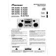
RRV2069
SPEAKER SYSTEM
S-A660
65S This service manual is intended for qualified service technicians; it is not meant for the casual do-it-yourselfer. Qualified technicians have the necessary test equipment and tools, and have been trained to properly and safely repair complex products such as those covered by this manual. Improperly performed repairs can adversely affect the safety and reliability of the product and may void the warranty. If you are not qualified to perform the repair of this product properly and safely, you should not risk trying to do so and refer the repair to a qualified service technician. WARNING Lead in solder in this product is listed by the California Health and Welfare agency as a known reproductive toxicant which may cause birth defects or other reproductive harm (California Health & Safety Code, Section 25249.5). When servicing or handling circuit boards and other components which contain lead in solder, avoid unprotected skin contact with the solder. Also, when soldering do not in hale any inhale any smoke or fumes produced.
XC
This product is component of system. For the operating instructions, refer to the service manual RRV2064 for XR-A660.
The woofer is attached to the cosmetic baffle assy together with the woofer ring assy by 4 internal screws. To detach the woofer (woofer ring assy), loosen these screws. To attach the woofer ring assy, fit the boss of the woofer ring to the hole of the cosmetic baffle assy. To attach the woofer, face its terminal downward, and fit the portion of the notch and hole of the frame to the bank and hole of the cosmetic baffle assy. To attach the woofer ring assy and woofer, replace it on the cosmetic baffle assy correctly and secure with 4 screws. The mid-range is attached to the cosmetic baffle assy by 2 internal screws. To detach the mid-range, loosen these screws. Then carefully disconnect the wires of the tweeter mounted on the cosmetic baffle assy by adhesion. To attach the mid-range, replace it on the cosmetic baffle assy correctly and secure with 2 screws. The network assy is attached to the back board of the cabinet by press-fitting. To detach the network assy, strike the cordstopper of the network assy with a hammer from inside of the cabinet. To attach the network assy, replace it on the back board of the cabinet correctly by press-fitting. When exchange the tweeter, do it with the cosmetic baffle assy.
FOR PRECAUTION OF REASSEMBLY AND DISASSEMBLY
The cosmetic baffle assy is attached to the cabinet by 4 external screws. To detach the cosmetic baffle assy, loosen these screws. Then carefully disconnect the wires of the woofer and mid-range mounted on the cosmetic baffle assy. To attach the cosmetic baffle assy, replace it on the cabinet correctly and secure with 4 screws.
PIONEER ELECTRONIC CORPORATION
4-1, Meguro 1-Chome, Meguro-ku, Tokyo 153-8654, Japan PIONEER ELECTRONICS SERVICE, INC. P.O. Box 1760, Long Beach, CA 90801-1760, U.S.A. PIONEER ELECTRONIC (EUROPE) N.V. Haven 1087, Keetberglaan 1, 9120 Melsele, Belgium PIONEER ELECTRONICS ASIACENTRE PTE. LTD. 253 Alexandra Road, #04-01, Singapore 159936
PIONEER ELECTRONIC CORPORATION 1998
T-ZZW DEC. 1998 Printed in Japan
|
|
|
> |
|