|
|
|
Categories
|
|
Information
|
|
Featured Product
|
|
|
 |
|
|
There are currently no product reviews.
 ;
The scan is clear and well readable with very few weaker spots, usually on black background with white letters, but with enough zoom those spots can be read.
Printout is clear, the manual is complete and has all pages scanned.
I would give 5 stars, except that it is not in color, and the schematic and PCB pages are scanned on multiple pages. The document is locked (except printing) so the pages can not be extracted to compose them together for printing on the large plotter
It is worth the price tag.
 ;
let's say first that i do not need to have a credit for my opinion, i am a retired sparkie and i voluteerd to fix an electronic device for a local "Youthgroup",as no diagram was present i checked the "net" and gambled on this site and paying some fee via PayPall, i was gladly surprised that the manual arrived as was stated, GOOD SHOW, and best wishes, John
;
I had been looking for a Manual for my CS2150 for quite a while -- in fact I had just about given up. I saw this site and decided to download the Manual. When I Received it by Email I was really pleased with what I got, with the result that My Kenwood 'Scope is now 100% repaired and working well. As an AV Serviceman, you need a good 'scope, and thanks to this site, and the Service Manual, I have been able to repair it. The Manual was a copy of the Factory Original and the copy was very clear, especially in the area of the Circuit Schematics, where You really need to be sure of what You are looking at.
;
I recently purchased a manual for a Samsung DLP tv to help with a trouble shooting problem I was having. Every tv repair shop wanted close to $400.00 for the fix, but after I found Owner-Manuals.com I hit pay dirt. The manual they had for me to purchase and download was a complete service manual for the exact tv I needed. It was complete with wiring diagrams, schematics, and even part numbers. If your the fix it yourself type I highly recommend trying to find any manual here before paying someone else to fix whatever problem your having.
;
Once again, excellent price and manual delivered in a timely manner and as advertised!
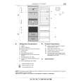
SA-AK330P / SA-AK330PC
10.12. Replacement for the pinch roller ass�y and head block
· Follow the (Step 1) - (Step 2) of Item 10.2 - Disassembly of Top Cabinet · Follow the (Step 1) - (Step 6) of Item 10.3 - Disassembly of CD Lid · Follow the (Step 1) of Item 10.4 - Disassembly of the Rear Panel · Follow the (Step 1) - (Step 3) of Item 10.5 - Disassembly of the CD Mechanism Unit · Follow the (Step 1) - (Step 3) of Item 10.9 - Disassembly of the Front Panel Unit · Follow the (Step 1) - (Step 5) of Item 10.10 - Disassembly of the Deck Mechanism Unit * The mechanism as shown below is for DECK1. For DECK 2, perform the same procedures. Step 1 Release the 2 claws, and then remove the pinch roller (R), (F). Step 2 Release ther 2 claws, and then remove the head connector.
Step 3 Remove 2 screws.
10.13. Replacement for the Deck motor ass�y, capstan belt A, capstan belt B and winding belt
· Follow the (Step 1) - (Step 2) of Item 10.2 - Disassembly of Top Cabinet · Follow the (Step 1) - (Step 6) of Item 10.3 - Disassembly of CD Lid · Follow the (Step 1) of Item 10.4 - Disassembly of the Rear Panel · Follow the (Step 1) - (Step 3) of Item 10.5 - Disassembly of the CD Mechanism Unit · Follow the (Step 1) - (Step 3) of Item 10.9 - Disassembly of the Front Panel Unit · Follow the (Step 1) - (Step 5) of Item 10.10 - Disassembly of the Deck Mechanism Unit Step 1 Release the 2 claws, and then remove the head connector. Step 2 De-solder plunger point. Step 3 Remove the Deck Mechanism P.C.B.
32
|
|
|
> |
|