|
There are currently no product reviews.
 ;
The delivery of this manual was very fast, less than 8 hours. The manual is very clear and concise, and helped a great deal in the repair and final setup of the Hitachi HMA-G2 Amplifier.
;
Great service. The manual was exactly what I was looking for: schematic + layout. I managed to fix the player. Highly recommended!
 ;
At $5,00 certainly good bang for your buck. Includes electric schematics as well as exploded parts view + parts list for reordering. Unfortunately no details on the PCB contents or working, but then again, this is not overly complex. Best bonus: this manual does contain the heavily searched for LED error codes as well as descriptions for test operation. Haven't gotten around to fixing the machine yet, one thing the manual won't do for you is getting it out of the kitchen assembly :-(
;
It`s not your fault tear down is rather incomplete. It doesn`t have complete instructions as to deconstruction for repair.
;
THANK YOU FOR A GOOD TRANSACTION, NICE COPY, CLEAR
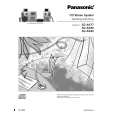
SA-AK77
� Installation of the CD servo P.C.B. after replacement Step 1 Connect the FFC board. Step 2 Install the CD servo P.C.B. in the traverse deck assembly.
Step 2 Remove the wires at CN302, CN303 and CN304 and pull out the Main P.C.B. Step 3 Remove 4 screws fixed to the Power Amplifier IC. Note: Before installing the CD servo P.C.B., move the optical pickup towards the outer edge from the marking (black triangle). [Otherwise, the reset detect switch (S701) mounted on the CD servo P.C.B. may be damaged.]
2. Replacement of the Power Amplifier IC Step 1 Follow the procedures in �Checking Procedure for each major P.C.B.� ( Step 1 - Step 4 ). Step 4 Unsolder the terminals of Power Amp IC and replace the respective component.
13
|