|
|
|
Categories
|
|
Information
|
|
Featured Product
|
|
|
 |
|
|
There are currently no product reviews.
 ;
perfect, i am very satisfait for the réception of the sansui r-5l service manual, thank you very much
;
Thank you, this is a rare document. Few others have it, but they charge way more for a download.
Great deal (even if you have to wait a few hours to get it).
;
The purchased manual is an high quality scan of the original Philips paper-based Service Manual. I am very satisfied!
 ;
The purchased manual is an scan of the original Panasonic paper-based Service Manual. Unfortunately the contrast is not perfect, but I am satisfied anyway!
;
The purchased manual is an high-quality scan of the original JVC paper-based Service Manual. The Service Manual includes the Owner´s Manual, so you do not have to buy both of them.
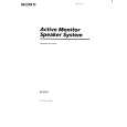
SAFETY CHECK-OUT After correcting the original service problem, perform the following safety checks before releasing the set to the customer: Check the antenna terminals, metal trim, �metallized� knobs, screws, and all other exposed metal parts for AC leakage. Check leakage as described below. LEAKAGE The AC leakage from any exposed metal part to earth Ground and from all exposed metal parts to any exposed metal part having a return to chassis, must not exceed 0.5 mA (500 microampers). Leakage current can be measured by any one of three methods. 1. A commercial leakage tester, such as the Simpson 229 or RCA WT-540A. Follow the manufacturers� instructions to use these instruments. 2. A battery-operated AC milliammeter. The Data Precision 245 digital multimeter is suitable for this job. 3. Measuring the voltage drop across a resistor by means of a VOM or battery-operated AC voltmeter. The �limit� indication is 0.75 V, so analog meters must have an accurate low-voltage scale. The Simpson 250 and Sanwa SH-63Trd are examples of a passive VOM that is suitable. Nearly all battery operated digital multimeters that have a 2V AC range are suitable. (See Fig. A)
To Exposed Metal Parts on Set
0.15µF
1.5k�
AC voltmeter (0.75V)
Earth Ground
Fig. A. Using an AC voltmeter to check AC leakage.
TABLE OF CONTENTS 1. GENERAL .......................................................................... 3 2. DIAGRAMS
2-1. 2-2. 2-3. 2-4. 2-5. 2-6. 2-7. Circuit Boards Location ........................................................ 4 Printed Wiring Board � WPC5 Section � ......................... 5 Schematic Diagram � WPC5 Section � ............................ 7 Printed Wiring Board � SPC5 (R) Section � ..................... 9 Schematic Diagram � SPC5 (R) Section � ..................... 11 Printed Wiring Board � SPC5 (L) Section � ................... 14 Schematic Diagram � SPC5 (L) Section � ...................... 17
SAFETY-RELATED COMPONENT WARNING !! COMPONENTS IDENTIFIED BY MARK ! OR DOTTED LINE WITH MARK ! ON THE SCHEMATIC DIAGRAMS AND IN THE PARTS LIST ARE CRITICAL TO SAFE OPERATION. REPLACE THESE COMPONENTS WITH SONY PARTS WHOSE PART NUMBERS APPEAR AS SHOWN IN THIS MANUAL OR IN SUPPLEMENTS PUBLISHED BY SONY.
3. EXPLODED VIEWS
3-1. SA-PC5 (R) Section ............................................................ 20 3-2. SA-PC5 (L) Section ............................................................ 21 3-3. SA-WPC5 (SUPER WOOFER) Section ............................ 22
4. ELECTRICAL PARTS LIST ........................................ 23
�2�
 $4.99 SASPC5 SONY
Owner's Manual Complete owner's manual in digital format. The manual will be available for download as PDF file aft…
|
|
|
> |
|