|
|
|
Categories
|
|
Information
|
|
Featured Product
|
|
|
 |
|
|
There are currently no product reviews.
 ;
the manual is in good quality and it's in pdf. manual was send in less then 24h.
regards
mike
;
I would not plug this machine in without finding a manual like this. In addition to setup and normal operating instructions, it has troubleshooting flowcharts, diagrammed mechanical adjustments, and schematics to beat the band. The tech I hand it to would be thrilled to find solder side PCB diagrams with component outlines superimposed, pinouts for every IC chip, and line drawings of transistors, with labeled legs.
As for printing quality, this may be a copy of a copy, but even the finest print when enlarged is very legible. There is a bit of grayed print over a few pages, as if a wet page were placed over it, but the print is still very legible. If you could borrow an original manual and get it printed and bound for 4 to 6 times the cost, you could get better quality. In that case you wouldn't be here. For price, utility, and availability I am rating this manual highly.
;
I received the Manual in a timely manner and it was exactly what I needed.
This is a perfect copy of the Service Manual, The quality is great. I am very
happy. Thank you
;
exactly as they say. Within 24 hours the link to the pages and offcourse it was the right service manual. Super and thanks
 ;
The manual was exact the thing that was promised. My old car stereo is working again thanks to the information supplied.
SAVA-27
TEST MODE
MODE ALL FLUORESCENT INDICATOR TUBES LIGHT
When the AC plug is inserted to the power outlet with pressing the MASTER VOL + button, the all fluorescent indicator tubes light.
SECTION 1 GENERAL
This section is extracted from instruction manual.
SECTION 2 DISASSEMBLY
2-1. REMOVAL AMPLIFIER BLOCK 3-1. CIRCUIT BOARDS LOCATION
SECTION 3 DIAGRAMS
2
!§ One connector PS Board
POW-SW board INPUT board
!� Back panel 8 5th tapping screws (4�16)
POWER board POW-SR board POW-CN board POW-L board
KEY CHECK, LED LIGHTING MODE
1. Pull out the AC plug from the power outlet and turn the power OFF. 2. Connect the lead wire to TP3 on the KEY board. 3. Insert the AC plug to the power outlet and set to STANDBY mode. 4. Let the lead wire connected in step 1 contact to the ground. 5. All fluorescent indicator tubes light, and enter the key check mode. 6. Pressing any buttons, the number of button will be displayed on the fluorescent indicator tube. 7. After all buttons are pressed, it will be in the STANDBY mode. Button POWER MASTER VOL� MASTER VOL + INPUT SURROUND CTR MODE S.WOOFER Note: 1. The LED (D505)lights while pressing each button. The LED lights in red when ever number of buttons are pressed, and it lights in green when odd number of buttons are pressed. 2. The LED lights even when the pressed button is pressed again. � Parts Location Button Number 2 3 4 5 6 7 8 LED Color Red Green Red Green Red Green Red
1
3
7 Display panel assembly
4
4
5 Four tapping screws
POW-R board DOLBY board
(4�20) SDN651
!¶ Amplifier
5
6 Flat type wire (27core)
MAIN board
PS board
DISPLAY board
9 8th tapping screws (4�16) !º Three tapping screws (4�16)
1 2 3 4
LEFT CHANNEL SPEAKER/CENTER CHANNEL WOOFER CENTER CHANNEL TWEETERS RIGHT CHANNEL SPEAKER/CENTER CHANNEL WOOFER SUPER WOOFER
1 Grill frame assembly
T1 board
KEY board
!¡ 6P connector
T2 board
5 REAR SPEAKER
!� 5th screws (BVTP 3�8)
!¶
[KEY BOARD] � Conductor side �
6 7 8 !§ !� 9
IC503
CN552
6 7 8 9 !º !¡ !� !£ !¢ !� !§ !¶ !� !ª @º @¡ @� @£ @¢ @�
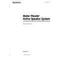
THEATER PRO LOGIC STADIUM GAME INPUT1 INPUT2 MUTING MASTER VOL SUPER WOOFER MODE (1, 2, OFF) SUR OFF HALL POWER POWER STANDBY indicator ON/READY indicator VOLUME S.WOOFER Remote Sensorg SURROUND INPUT
2 Ornament frame 4 Front frame assembly 3 Three tapping screws (4�20) !£ Four screws (BVTP 3�8) !¢ Two screws
(BVTP 3�8)
S506 R557 TP3
!º !¡ !� !ª @º
!¢ !£
@¡
!�
@� @¢
@£
@�
�3�
�4�
�5�
�6�
 $4.99 SAVA27 SONY
Owner's Manual Complete owner's manual in digital format. The manual will be available for download as PDF file aft…
|
|
|
> |
|