|
|
|
Categories
|
|
Information
|
|
Featured Product
|
|
|
 |
|
|
There are currently no product reviews.
 ;
This manual was the factory original. Excellent value and contained all the details I needed. Easy dowwnload provided the information when I needed it.
 ;
Impeccable, document très complet. Perfect, i get all i need. All schematic are correct. Thanks
;
The manual is of better quality compared to other. I found it less expensive and therefore it it is the best buy cost vs quality.
;
I bought the service-manual of the sony ICB-1020(an old transmitter-receiver) at "www.Owners-Manual.com", I found the service-manual for a fairly cheap price(in comparison with other sellers). I filled in some questions, payed the order with Ideal, and within 24 hours I had my service manual. I was very happy:In no time I had my service-manual and everything, but literally everything was noted down in the manual; the electronic scheme, the parts list, etcetera.
A very practical, reference-document.
;
This comprehesive service maual was greatly appreciated, as was the digital download.
SA-VE335/WMS335/SS-CN335/V335
SAFETY CHECK-OUT
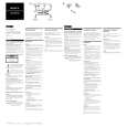
After correcting the original service problem, perform the following safety check before releasing the set to the customer: Check the antenna terminals, metal trim, �metallized� knobs, screws, and all other exposed metal parts for AC leakage. Check leakage as described below. LEAKAGE TEST The AC leakage from any exposed metal part to earth ground and from all exposed metal parts to any exposed metal part having a return to chassis, must not exceed 0.5 mA (500 microamperes). Leakage current can be measured by any one of three methods. 1. A commercial leakage tester, such as the Simpson 229 or RCA WT-540A. Follow the manufacturers� instructions to use these instruments. 2. A battery-operated AC milliammeter. The Data Precision 245 digital multimeter is suitable for this job. 3. Measuring the voltage drop across a resistor by means of a VOM or battery-operated AC voltmeter. The �limit� indication is 0.75 V, so analog meters must have an accurate low-voltage scale. The Simpson 250 and Sanwa SH-63Trd are examples of a passive VOM that is suitable. Nearly all battery operated digital multimeters that have a 2V AC range are suitable. (See Fig. A)
TABLE OF CONTENTS 1. DIAGRAMS
1-1. Circuit Boards Location (SA-WMS335) ............................ 3 1-2. Printed Wiring Boards (SA-WMS335) ............................... 5 1-3. Schematic Diagram (SA-WMS335) ................................... 6
2. EXPLODED VIEWS
2-1. 2-2. 2-3. 2-4. Front Panel Section (SA-WMS335) .................................... 7 Rear Panel Section (SA-WMS335) ..................................... 8 Front and Rear Speaker (SS-V335) ..................................... 9 Center Speaker (SS-CN335) ............................................. 10
3. ELECTRICAL PARTS LIST ........................................ 11
To Exposed Metal Parts on Set
0.15µF
1.5k�
AC voltmeter (0.75V)
Earth Ground
Fig. A. Using an AC voltmeter to check AC leakage.
SAFETY-RELATED COMPONENT WARNING!! COMPONENTS IDENTIFIED BY MARK 0 OR DOTTED LINE WITH MARK 0 ON THE SCHEMATIC DIAGRAMS AND IN THE PARTS LIST ARE CRITICAL TO SAFE OPERATION. REPLACE THESE COMPONENTS WITH SONY PARTS WHOSE PART NUMBERS APPEAR AS SHOWN IN THIS MANUAL OR IN SUPPLEMENTS PUBLISHED BY SONY.
ATTENTION AU COMPOSANT AYANT RAPPORT � LA S�CURIT�!! LES COMPOSANTS IDENTIFI�S PAR UNE MARQUE 0 SUR LES DIAGRAMMES SCH�MATIQUES ET LA LISTE DES PI�CES SONT CRITIQUES POUR LA S�CURIT� DE FONCTIONNEMENT. NE REMPLACER CES COMPOSANTS QUE PAR DES PI�CES SONY DONT LES NUM�ROS SONT DONN�S DANS CE MANUEL OU DANS LES SUPPL�MENTS PUBLI�S PAR SONY.
2
|
|
|
> |
|