|
|
|
Categories
|
|
Information
|
|
Featured Product
|
|
|
 |
|
|
There are currently no product reviews.
 ;
Manual was just as described!!! I odered it and in less than a day was able to download it and the text was clear and pages were all complete just as the original manual was. Purcashed this for a friend and they were more than happy. Perfect all around!
 ;
Excellent service and prompt delivery. But it's not a manual - only 4 pages wiring diagrams.
Thanks.
;
The manual I purchased was exactly what I needed to repair my Toshica television. The manual contained schematics and troubleshooting information that was very helpful.
;
Il download del Service Manual JVC HR 4100 non é stato eseguito
;
The Service Manual was just as expected, complete with schematics and I was able to download it in less than an hour after I ordered it. The only problem with these is that the schematics are hard to read due to the small font. I could remedy this by printing them on a larger printer.
INC
FSA03301-R.3564.A
� There are high voltege parts inside. Be careful of this electric shock, when you remove the cover. � Do not attach the screw longer than M1.7 x 5.5 to the hole for measurement of main condenser voltage because there is high voltage part inside.
� Confirmation of the main condenser voltage: Standard value: 330 ± 10V � It is possible to measure voltage by inserting a thin probe in the hole for measurement of the main condenser. (Hole for measurement - GND) � � For safety, be careful of high voltage. The following calculation is needed. � Main condenser voltage = Meaured value x (1 + 470k Ω / Input impedance of the meter) e.g.: When an input impedance of the meter (resistance) is 10M Ω and a measured value is 315V, 315�1.047 = apporox. 330V. * Input impedance of the meter (resistance) is indicated on the bottom face of the meter or in the instruction manual. � Confirmation of the safety circuit operation voltage: Standard value: The safety circuit operates at between 341V � 360V and this SB fires fully. It is possible to confirm the operation voltage of the safety circuit by oscillating with the MO terminal connected with the GND so that oscillation does not stop even the main condenser voltage reaches 330V. After the adjustment, attach the screw to the hole for measurement of the main condenser voltage. � Adjustment of the flash output level for non-TTL auto flash: Standard value : ±1EV at every position of the followings Rotate the VR1 slowly so that the value would be F5.6 at the F5.6 position. After the adjustment, confirm it at the other positions (F2.8, F4, F8) and they should satisfy the standard.
Standard reflector 2m
Flash meter
�
Adjustment of the manual auto flash level: Standard value : M1/1=GN16±0.5EV � �M1/8=GN5.6±0.5EV � �M1/32=GN2.8±0.5EV Rotate the VR2 slowly so that would be GN=5.6 at the position of M1/8. After the adjustment, confirm the value at another position (M1/32) and it should satisfy the standard. - A2 ・ SB-30 -
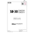 $4.99 SB-30 NIKON
Parts Catalog Parts Catalog only. It's available in PDF format. Useful, if Your equipment is broken and You need t…
|
|
|
> |
|