|
|
|
Categories
|
|
Information
|
|
Featured Product
|
|
|
 |
|
|
There are currently no product reviews.
 ;
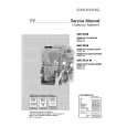
German user manual with schematics
GREAT INFORMATION AT VERY LOW PRICE!
A++
;
Excellent printing quality.
A complete and very usefull service manual with all details.
GREAT SERVICE AT VERY LOW PRICE!
A++
;
Excellent printing quality.
A complete and very usefull service manual with all details.
GREAT SERVICE AT VERY LOW PRICE!
A++
;
Excellent printing quality.
A complete and very usefull service manual with all details.
GREAT SERVICE AT VERY LOW PRICE!
A++
;
Excellent printing quality.
A complete and very usefull service manual with all details.
GREAT SERVICE AT VERY LOW PRICE!
A++
SB-WA880GC / SB-WA880GCT
2 Before Use
Be sure to disconnect the mains cord before adjusting the voltage selector. Use a minus (-) screwdriver to set the voltage selector (on the rear panel) to the voltage setting for the area in which the unit will be used. (If the power supply in your area is 117V or 120V, set to the �127V� position.) Note that this unit will be seriously damaged if this setting is not made correctly. (There is no voltage selector for some countries; the correct voltage is already set.)
3 Before Repair and Adjustment
Disconnect AC power, discharge Power Supply Capacitors C546~C549 through a 10 �, 1 W resistor to ground. DO NOT SHORT-CIRCUIT DIRECTLY (with a screwdriver blade, for instance), as this may destroy solid state devices. After repairs are completed, restore power gradually using a variac, to avoid overcurrent. Current consumption at AC100/110V, 50/60 Hz in NO SIGNAL mode should be ~1180 mA. Current consumption at AC 230-240V, 50 Hz in NO SIGNAL mode should be ~600 mA.
4 Protection Circuitry
The protection circuitry may have operated if either of the following conditions are noticed: · No sound is heard when the power is turned on. · Stops during a performance. The function of this circuitry is to prevent circuitry damage if, for example, the positive and negative speaker connection wires are �shorted�, or if speaker systems with an impedance less than the indicated rated impedance of the amplifier are used. If this occurs, follow the procedure outlines below: 1. Turn off the power. 2. Determine the cause of the problem and correct it. 3. Turn on the power once again after one minute. Note: When the protection circuitry functions, the unit will not operate unless the power is first turned off and then on again.
5 Handling the Lead-free Solder
5.1. About lead free solder (PbF)
Distinction of PbF P.C.B. : P.C.B.s (manufactured) using lead free solder will have a PbF stamp on the P.C.B. Caution: · Pb free solder has a higher melting point than standard solder. Typically the melting point is 50 - 70°F (30 - 40°C) higher. Please use a high temperature soldering iron. In case of the soldering iron with temperature control, please set it to 700 ± 20°F (370 ± 10°C). · Pb free solder will tend to splash when heated too high (about 1100°F/600°C). · When soldering or unsoldering, please completely remove all of the solder on the pins or solder area, and be sure to heat the soldering points with the Pb free solder until it melts enough.
4
|
|
|
> |
|