|
|
|
Categories
|
|
Information
|
|
Featured Product
|
|
|
 |
|
 ;
Clear and concise. Saved me a lot of time and money.
 ;
We received the manual in a timely manner and it was exactly what we were expecting. Excellent replacement for original Service Manual.
All schematics are very legible. We are really satisfied.
;
We received the manual in a timely manner and it was exactly what we were expecting. Excellent replacement for original Service Manual.
All schematics are very legible. We are really satisfied.
;
We received the manual in a timely manner and it was exactly what we were expecting. Excellent replacement for original Service Manual.
All schematics are very legible. We are really satisfied.
;
We received the manual in a timely manner and it was exactly what we were expecting. Excellent replacement for original Service Manual.
All schematics are very legible. We are really satisfied.
;
We received the manual in a timely manner and it was exactly what we were expecting. Excellent replacement for original Service Manual.
All schematics are very legible. We are really satisfied.
ScanCopier
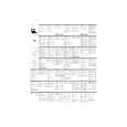
8.3.6 OPTICAL CHASSIS
DISASSEMBLING PROCEDURE
(1) (2) (3) (4) Remove the upper housing. ( See section 8.3.3 ) Remove the main control PCBA. (See section 8.3.4) Remove the cable clamp for the CCD flat cable. Disconnect the motor belt by releasing the belt spring. (See section 8.3.5) Lift the sliding rod and pull it out. Belt spring Optical chassis
(5)
Sliding rod Motor belt
CCD flat cable
Figure 8.6 Optical chassis removal
Attention: Do not remove the flat cable from the optical chassis.
ASSEMBLING PROCEDURE Assemble the part in reverse order of the disassembling procedure. Note: � Do not remove the flat cable from the optical chassis as the flat cable need special tool to reinstall it. � Any unauthorized action may cause unexpected result and will therefore not be responsible by the manufacturer.
8-8
|
|
|
> |
|