|
|
|
Categories
|
|
Information
|
|
Featured Product
|
|
|
 |
|
|
There are currently no product reviews.
 ;
Very nice and real Service Manual, I didn't thought it actually exist in the real world at all.
 ;
VERY NICE FOR COURTESY AND PRECISION!.
tHE SITE IS VERY IMPORTANT FOR ALL DEVICES
vERY GOOD
;
+++ Is is fine, that was what i looking for. Thanks! +++
;
A very good complete archive, i am very satisfied for document.
;
The Service Manual received was helpful. The electronic information is exactly what I needed.
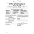
1-3-4. Sub Chassis (with a pickup mechanism) 1. Turn the mechanism chassis assembly (1) upside down. 2. Remove one screw (2) and release the boss �A� from the claw. Then remove the sub chassis (3) (with the pickup mechanism) by sliding in the arrow direction. 3. When mounting, perform the reverse order of the removal. Note: � When mounting the sub chassis (3) (with the pickup mechanism), first, insert the boss �C� along the groove of the cam slider up/down cam (4) and next, the boss �B� and �A�. � The boss �A� may be used with washers. (One or two washers are used to prevent from the slust rattling. In some cases, no washer is used.) When the washer(s) is used, be sure to assemble as it was without losing.
Screw (2) Sub chassis (3) (with the pickup mechanism attached) Boss C
1-3-5. Pickup Mechanism Assembly <Removal> 1. Remove four screws (1) and then remove the pickup mechanism assembly (2). <Mounting> 1. Replace the pickup mechanism assembly (2) with a new one. 2. When mounting, perform the reverse order of the removal.
Screw (1)
Damper (Black) Damper (Blue)
Damper (Black)
Boss A
Damper (Blue) Pickup mechanism assembly (2)
Washers Boss B
Cam slider up/down cam (4)
Groove
Fig. 2-1-17 Note:
Mechanism chassis assembly (1)
Claw
Groove Boss A
� The dampers� color differs when used for the front side and the rear. � When mounting the pickup mechanism assembly (2) with the screws (1), push the pickup mechanism assembly (2) downward without being caught and tighten the screws (1).
Screw (1)
Claw Boss B Groove
Damper Pickup mechanism assembly (2)
Fig. 2-1-16
Fig. 2-1-18
|
|
|
> |
|