|
|
|
Categories
|
|
Information
|
|
Featured Product
|
|
|
 |
|
|
There are currently no product reviews.
 ;
Manual is actually a pack of schematics, good quality pictures.
;
Great service. Manual delivered at a great price. Reliable delivery service. They have a great selection. A recommended service!
 ;
I used your service and I found myself well I need service manual teac v plate 770 and I was able to access and remove the belt that erno routes. thanks I recommend it to all
;
At first I thought there had been a mix up as I required the service manual for the cassette unit and the one supplied was for the CD unit. However when I scrolled further down I realised that both had been scanned together! This enabled me to dismantle and repair the cassette unit as intended and I also have a copy of the manual for both the CD and graphic equaliser units should I ever need them. Thanks very much for a great service.
;
Excelent service, the manual is complete, very cheap and fast
Alberto
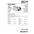
GUIDE UP/DOWN
GEAR LOADING
(L3)
(L6)
GEAR PULLEY (L6)
(L4)
BASE MAIN BELT LOADING PWB ASSEMBLY LOADING (H1)
(L6)
(S5)
BASE MAIN
(A) (A) (B) (L5) FIG. (A) (C) (B) GUIDE UP/DOWN GUIDE UP/DOWN (A) (B) (S4) FRAME ASSEMBLY UP/DOWN
GUIDE UP/DOWN
FIG. (B)
FIG. (C)
Fig. 4-4
5. Frame Assembly Up/Down
Note Put the Base Main face down(Bottom Side) 1) Release the Screw(S4) 2) Unlock the Locking Tab(L3) in direction of arrow and then lift up the Frame Assembly Up/Down to separate it from the Base Main. Note � When reassembling move the Guide Up/Down in direction of arrow(C) until it is positioned as Fig.(C). � When reassembling insert (A) portion of the Frame Assembly Up/Down in the (B) portion of the Guide Up/Down as Fig.(B)
8. Gear Loading (Fig. 4-4) 9. Guide Up/Down (Fig. 4-4)
1) Move the Guide Up/Down in direction of arrow(A) as Fig.(A) 2) Push the Locking Tab(L5) down and then lift up the Guide Up/Down to separate it from the Base Main. Note When reassembling place the Guide Up/Down as Fig.(C) and move it in direction arrow(B) until it is locked by the Locking Tab(L5). And confirm the Guide Up/Down as Fig.(A)
10. PWB Assembly Loading
Note Put the Base Main face down(Bottom Side) 1) Release 2 Screws(S5) 2) Unkool the Loading Motor Connector (C2) from the Hook (H1) on the Base Main. 3) Unlock 2 Locking Tabs(L6) and separate the PWB Assembly Loading from the Base Main.
6. Belt Loading(Fig. 4-4)
Note Put the Base Assembly Main on original position(Top Side)
7. Gear pulley (Fig. 4-4)
1) Unlock the Locking Tab(L4) in direction of arrow(B) and then separate the Gear Pulley from the Base Main.
11. Base Main(Fig. 4-4)
- 2-72 -
|
|
|
> |
|