|
|
|
Categories
|
|
Information
|
|
Featured Product
|
|
|
 |
|
|
There are currently no product reviews.
 ;
The purchased manual is an high-quality scan of the original JVC paper-based Service Manual. The Service Manual includes the Owner´s Manual, so you do not have to buy both of them.
 ;
It paid to find this Service Manual, couldn't find it anywhere else. Exactly what I wanted. Received within 24 hours.
;
Complete manual with clear schematic diagrams and printed circuit board layouts of two variants of the headset and the transmitter an old and a new version.
Also shows how the headset and the transmitter is opened and how transmitter and receivers can be adjusted and where to measure.
I had no problems to repair the headset using this service manual.
;
Excellent printing quality. A complete and very useful manual with all details.
;
This is a great site. I placed my order and by the next am it was available for download. Had some problems with some missing copy on some pages. Once I brought the error to the OMC's attention, the issue was resolved. I'll come back again.
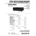
DECK MECHANISM DISASSEMBLY
Fig. 4-4
5. Frame Assembly Up/Down (Fig. 4-4)
Note Put the Base Main face down(Bottom Side) 1) Release the Screw(S4) 2) Unlock the Locking Tab(L3) in direction of arrow and then lift up the Frame Assembly Up/Down to separate it from the Base Main. Note � When reassembling move the Guide Up/Down in direction of arrow(C) until it is positioned as Fig.(C). � When reassembling insert (A) portion of the Frame Assembly Up/Down in the (B) portion of the Guide Up/Down as Fig.(B)
8. Gear Loading (Fig. 4-4) 9. Guide Up/Down (Fig. 4-4)
1) Move the Guide Up/Down in direction of arrow(A) as Fig.(A) 2) Push the Locking Tab(L5) down and then lift up the Guide Up/Down to separate it from the Base Main. Note When reassembling place the Guide Up/Down as Fig.(C) and move it in direction arrow(B) until it is locked by the Locking Tab(L5). And confirm the Guide Up/Down as Fig.(A)
10. PWB Assembly Loading (Fig. 4-4)
Note Put the Base Main face down(Bottom Side) 1) Release 2 Screws(S5) 2) Unlock the Loading Motor (C2) from the Hook (H1) on the Base Main. 3) Unlock 2 Locking Tabs(L6) and separate the PWB Assembly Loading from the Base Main.
6. Belt Loading(Fig. 4-4)
Note Put the Base Main on original position(Top Side)
7. Gear pulley (Fig. 4-4)
1) Unlock the Locking Tab(L4) in direction of arrow(B) and then separate the Gear Pulley from the Base Main.
11. Base Main(Fig. 4-4)
4-4
|
|
|
> |
|