|
|
|
Categories
|
|
Information
|
|
Featured Product
|
|
|
 |
|
|
There are currently no product reviews.
 ;
It´s very very nice manual with all, what i need. Original in good quality. Very fast business. Very much thanks...
;
Purchased the manual that I was looking for at a great price and could download it easily.. Great service experience and for future purchases I plan to use the site.
Thank you very much
;
Exactly what was needed to assess the product - excellent value and great service
;
A site where discontinualed schematic diagrams and back dated information can be found on discontinued radios tv's and any electronic equipment can be found. Newer manuals either Service and operating manuals. Radio amateurs should find this site a great source for ham radio equipment manuals. I will return to this site should I need information on any electrical equipment. priced easy to download in a PDF format and print pages need to undertake the repair.
;
Quality scan of the original. All the detail necessary to troubleshoot, repair and adjust the unit. I'm sure I will be downloading more manuals in the future as the need arises.
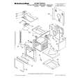
SD-CX1W
� The triangular wave for focus servo does not appear.
Is +3.3 V applied to pin 6 on IC3 ? No Yes Does the triangular wave appear at pin 33 on IC3 ? <Refer to the waveform diagrams on page 71.> Yes Does the triangular wave appear at pin 13 of IC1 ? <The same waveform as above> Yes Does the saw tooth wave appear between pins 3 and 4 of IC1 ? <Refer to the waveform diagrams on page 71.> Yes Does the saw tooth wave appear between pins 3 and 4 of CNS2 ? <The same waveform as above> Yes The PWB pattern has been cut. No The connection of CNS2 is poor or the optical pickup is defective. Check the parts around IC1 and the power supply line. IF OK, IC1 is defective. No The connection of signal lines between pin 33 on IC3 and pin 13 on IC1 is poor. No Check the parts around pin 33 on IC3. If OK, IC3 is defective. The +3.3 V line of IC3 is defective.
No
� The disc motor CLV servo is defective.
Does the disc motor rotate in the CD test mode 3 ? Yes
No
Is the voltage applied between pins 27 and 28 of IC1 for about 0.3-1.5 seconds when switching from the CD test mode 2 to 3 ?
Yes
The disc motor is defective or wires have broken.
0.3 ~ 1.5 seconds
No
Does the disc motor rotate too rapidly or slowly ? Yes
Is the pin 41 on IC3 in the high state for 0.3-1.5 seconds and does it pulse when switching from the CD test mode 2 to 3 ? <Refer to the waveform diagrams on page 70.> Yes
No
IC3 is defective.
5V 0.3 ~ 1.5 seconds
C3 is defective or wires have broken. Does the eye pattern appear at pin 19 on IC2 ? <Refer to the waveform diagrams on page 70.> (It is OK even if the waveform is not clear.) Yes (Vp-p 1.2 V waveform) Recheck whether the optical pickup objective is dirty. If it is dirty, clean it. Check the connection between pin 19 on IC2 and pin 24 on IC3. If OK, the optical pickup is defective.
No
Is the eye pattern Vp-p 1.2 V inputted to the pin 24 on IC3 ? Yes
No
Check the PWB pattern and C33.
IC3 is defective. (After checking the parts around it, replace it.)
� 75 �
 $4.99 SDCX1W SHARP
Owner's Manual Complete owner's manual in digital format. The manual will be available for download as PDF file aft…
|
|
|
> |
|