|
|
|
Categories
|
|
Information
|
|
Featured Product
|
|
|
 |
|
|
There are currently no product reviews.
 ;
The manual was a perfect match and was exactly what I was looking for. I'm very satisfied with my purchase.
;
Thank you for having the manual I needed for an older model Aiwa stero I had found on Ebay --- I wanted the Aiwa because I had tapes and cd's but I did not have a manual as to how to operate the system... I found what I needed and it has enabled me to set the system up for my enjoyment.
;
I wished detailed information of the JBL S310 and here I found it! Very happy with the service from this site!
;
The manual was very helpfull, it answerdes all my questions, and i was surprized to find the original manual on this site! Big thumbs uP:)
 ;
helpful manual.good service.Quick response.will use again
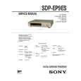
3-2. Display of History of DSP Operations � When �DSP error detected!� is displayed on the fluorescent display tube, the history of DSP errors will be displayed eight seconds later. (See Fig. 1.) � This history will be displayed if a DSP error has occurred in the past. It helps the detection of malfunction parts by enabling past problems of the unit to be checked. � This history shows the �Cause of error� and �How many times occurred� for the two DSPs. (See Fig. 1.)
4. Operation Check Mode � During the operation check mode, functions can be set by pressing the corresponding button. (See Table-3.) � Each time a button is pressed, the corresponding function will be displayed for about 8 seconds. � Buttons other than those displayed in Table-3 operate usually. NOTE: Do not press the SET UP button during the operation check mode. As this button is provided with a special function for debugging, pressing it may impede the normal output of signals in the sub-woofer mode. Table-3:
Fluorescent Display Tube Display
Fig. 1
Corresponding DSP Contents of fluorescent display tube How to read the display : 1st DSP (DSP56009) 2nd DSP (SSP424023) : 123x0000 � ���� 4321 123x0000 ���� � 4321 DIGITAL2
Button
Function
:
Number of times the error has occurred
DIG-2 Outputs the Lch DIGITAL-2 input signal to (L-SL, R-SR) the REAR Lch and the Rch to the REAR Rch. Outputs the Lch DIGITAL-3 input signal to DIG-3 (L-C, R-SW) the CENTER and the Rch only to the WOOFER.
How to read the display � The left side shows the errors of the first DSP (DSP56009:MAIN board IC424) and the right side shows the errors of the second DSP (SSP424023:MAIN board IC423). � The �How many times occurred� indicates the number of times that the error has occurred. If an error has occurred more than 256 times, it will be displayed as 256. � The 1 2 3 4 part shows 0 or 1 according to the cause of the error. If an error has occurred, 1 will be displayed. If no error has occurred, 0 will be displayed. (See Table-2.) Table-2:
Cause of error 1 Failed in initial booting 2 DSP does not operate 3 Communication port malfunction Possible cause Mostly due to faulty connection (soldering) between DSP and microprocessor Faulty DSP clock (X401 and onwards), faulty DSP part, etc. Overrunning of DSP due to heat, microprocessor bugging, or IC301 (MAIN board PLL) is faulty
DIGITAL3
DIGITAL4
DIG-4 (L, R-ALL)
Outputs the Lch DIGITAL-4 input signal to the FRONT Lch, REAR Lch, CENTER, and the Rch to the FRONT Rch, REAR Rch, and CENTER.
OFF
Whole fluorescent display tube lit check Each time the button is pressed, the fluorescent display tube lights up as follows. Lit totallynLit partially 1nLit partially 2nLit totally....
By pressing the MENU knob and displaying �<<< LEVEL ADJUST >>>�, and rotating the +/� knob to the right, the input signal selected at that time can be output to any Lch or Rch channel. (See Table-4.)
Table-4:
Fluorescent Display Tube Display Exchange (L-SL, R=SR) Output Destination of Input Signal Outputs the FRONT Lch/Rch signal only to the REAR Lch/Rch. Outputs the FRONT Lch signal only to the REAR Lch, and FRONT Rch signal to the REAR Rch. Outputs the FRONT Lch/Rch signal to the FRONT Lch/Rch, the REAR Lch/Rch signal to the REAR Lch/Rch, the CENTER signal to CENTER, and the WOOFER signal to WOOFER as usual. Outputs the FRONT Lch signal to the FRONT Lch, REAR Lch, and CENTER, and the FRONT Rch signal to the FRONT Rch, the REAR Rch, WOOFER.
4 No reply from DSP Faulty DSP part, or faulty microprocessor part, etc.
NOTE: This history is memorized in the EEPROM until the unit is initialized. (Refer to �5. Initialization� on page 14.)
Exchange (L-C, R=SW)
Exchange (NORMAL)
Exchange (L, R-ALL)
� 13 �
|
|
|
> |
|