|
|
|
Categories
|
|
Information
|
|
Featured Product
|
|
|
 |
|
|
There are currently no product reviews.
 ;
This is a very good quality print (scan) of the original SONY service manual. The original from Sony is on very thin paper. Nevertheless it is very clear and sharp and excellent readable. I'm very satisfied to have now this rare document. I've looking for it many years (infrequent). It contains very detailed circuit diagrams, exploded views, part lists, PCB view with good readable connection lines. Very recommended.
;
A complete manual with all the needed details of calibrations and service instructions about the radio receiver.
A big deal.
Many thanks !
;
Fast delivery and good quality copy. To be recommended
;
Excellent product, very clear print. Detailed circuit and assembly diagrams - this enabled me to repair my CD player with confidence. I highly recommend this site.
;
Fast access, 100% correct and complete service manual
Front
Surround
Subwoofer
Center
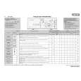
ORDER NO.
RRV3416
SPEAKER SYSTEM
S-DV353
S-DV353
XJC/NC
XJC/E
1. REASSEMBLY AND DISASSEMBLY PRECAUTIONS
FRONT / SURROUND SPEAKER
The grille is attached to the cabinet by 6 external screws. To detach it, unfasten those screws. The speaker unit, together with the grille, is attached to the cabinet by 4 external screws. To detach it, first unfasten those screws. Next remove the cabinet. Then remove the cable. When attaching it, face its terminal downward.
CENTER SPEAKER
The grille assy is attached to the cabinet by 8 external screws. To detach it, unfasten those screws. The speaker unit, together with the grille assy, is attached to the cabinet by 4 external screws. To detach it, first remove the grille assy. Next remove the cabinet. Then remove the cable. When attaching it, face its terminal toward the input terminal.
SUBWOOFER
The speaker unit is attached to the back board by 4 external screws. To detach it, unfasten those screws. When attaching it, face its terminal rightward. The cosmetic baffle assy is attached to the baffle board by its bosses applied with adhesive. To detach it, pry it open by inserting a flat blade screwdriver into lower slot. To attach it, apply adhesive to the holes on the baffle board. Then press it to the baffle board.
PIONEER CORPORATION
4-1, Meguro 1-chome, Meguro-ku, Tokyo 153-8654, Japan PIONEER ELECTRONICS (USA) INC. P.O. Box 1760, Long Beach, CA 90801-1760, U.S.A. PIONEER EUROPE NV Haven 1087, Keetberglaan 1, 9120 Melsele, Belgium PIONEER ELECTRONICS ASIACENTRE PTE. LTD. 253 Alexandra Road, #04-01, Singapore 159936
PIONEER CORPORATION 2006
T � ZZS JUNE 2006 Printed in Japan
|
|
|
> |
|