|
|
|
Categories
|
|
Information
|
|
Featured Product
|
|
|
 |
|
|
There are currently no product reviews.
 ;
Very helpful and complete manual. Maybe only one negative is schematics have sometimes unreadable name of the parts. But it's not a big problem.
 ;
Excellent high quality schematics brought my old Heidelberg back to life. Fast download at a reasonable price. Thanks.
;
This document is just what I was looking for, it´s very useful, it contains adjustment procedures for the final stage of the power amp and also
has a complete wiring diagram and description of the main semiconductors used in the design.
;
Dear Sirs,
Thank you for the fast support, the manual does provide all necessary information to repair the radio. All schematics are in a good quality for reading.
The manual fits 100% to my requirements as a technican.
Kind regards Thomas
;
the big video recorder format s-vhs many features delicate in loading system of the cassette. Such machines are no longer manufactured, it would be too expensive.
1
2
3
4
S-DV55SW-K, S-DV55SW-Q
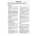
3. PCB CONNECTION DIAGRAM
3.1 AF ASSY
A
NOTE FOR PCB DIAGRAMS :
1. Part numbers in PCB diagrams match those in the schematic diagrams. 2. A comparison between the main parts of PCB and schematic diagrams is shown below.
Symbol In PCB Diagrams Symbol In Schematic Diagrams B CEB CE Part Name
A AF ASSY
To Power Transformer
B CN3302
BCE B BCE D DGS GSD GS C EB C E
Transistor
Transistor with resistor
Field effect transistor
Resistor array
B
3-terminal regulator
3. The parts mounted on this PCB include all necessary parts for several destinations. For further information for respective destinations, be sure to check with the schematic diagram. 4. View point of PCB diagrams.
Connector
Capacitor
SIDE A
P.C.Board
C
Chip Part
SIDE B
IC13 IC14 IC15 IC12 IC11
IC16
Q61
D
16
A
1 2 3 4
|
|
|
> |
|