|
|
|
Categories
|
|
Information
|
|
Featured Product
|
|
|
 |
|
|
There are currently no product reviews.
 ;
The service manual is as described and received the link to the download sooner than expected. Great service, quality product. This site is a big help in the electronics repair business.
;
Il service manual molto accurato. Rapidi nella risposta
;
Quick site processing. A complete and very useful manual with all details. Thank you!
;
Quick service response. A useful and very rare service manual with all details. I recomend this service.
;
I ordered this manual sometime in the afternoon and I received it on my e-mail the same evening.
This is a fantastically good and properly scanned copy of the original manual. All pages are of the same scale and they overlap each other. It means that you can print the manual and easily make it as a convenient paper manual.
The content of the manual is fantastic. Alignment descriptions, PCB layouts and elementary diagrams are explicit and precise. I immediately found what I was looking for. Thanks to this manual and Owner-Manuals.com my amplifier is alive again. Many thanx indded!
S-DV77, S-DV77SW, S-DV77ST
7. GENERAL INFORMATION
7.1 DISASSEMBLY
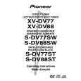
1. Removing the Amplifier Assy
1) The Amplifier Assy is attached to the cabinet by 6 external screws 1. To detach it, pull down the subwoofer toward the left side. 2) Then unfasten those screws 1 . 3) Then stand up the speaker again. To detach the Amplifier Assy, first remove the connecting code. Then pull straight the Amplifier Assy toward back and remove it.
Screw1 Screw1
2. Removing the Subwoofer
1) The speaker element is attached to the back board by 4 external screws 2.To detach it, unfasten those screws. 2) When attaching it,face its terminal upward.
3. Removing the Cosmetic Baffle
1) The cosmetic baffie is attached to the baffle by press-fitting. To detach it,pry it open by inserting a flat blade screwdriver into lower side.
Screw2
Screw2 Connecting Code
Amplifier Assy
4. Removing the Cosmetic Duct
1) The cosmetic baffle, those screws are removed when removing the cosmetic duct attached in cosmetic baffle with 8 screws.
33
|
|
|
> |
|