|
|
|
Categories
|
|
Information
|
|
Featured Product
|
|
|
 |
|
|
There are currently no product reviews.
 ;
Quick site processing. A complete and very useful manual with all details. Thank you!
;
Das Service Manual war von der ersten bis zur letzten Seite sehr informativ und hilfreich. Die Darstellung aller Teile war klar und der Text gut lesbar.
Vielen Dank, das war nicht der letzte Download bei ownner-manuals.com.
;
It's a grate service manuals.Have many details and the writing it's so clear.You have all you want in manual,nothing missing,belive me.I'm verry satisfied of this manual.
;
Great scanned service manual
Usefull informations.
I will buy again!
Best Regards
;
The manual describes this product very good. It has the basic things to know and also a more detailed look. Very well made!
5
6
7
8
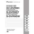
7.1.2 DISASSEMBLY
1. Removing the Amplifier Assy
1) The Amplifier Assy is attached to the cabinet by six external screws 1. To detach it, pull down the subwoofer toward the left side. 2) Then unfasten those screws 1 . 3) Then stand up the speaker again. To detach the Amplifier Assy, first remove the connecting code. Then pull straight the Amplifier Assy toward back and remove it.
A
2. Removing the Subwoofer
1) The speaker element is attached to the back board by four external screws 2. To detach it, unfasten those screws. 2) When attaching it,face its terminal upward.
Screw 1 Screw 1
B
3. Removing the Cosmetic Baffle
1) The cosmetic baffie is attached to the baffle by press-fitting. To detach it,pry it open by inserting a flat blade screwdriver into lower side.
Screw 2
Screw 2 Connecting Code
Amplifier Assy
4. Removing the Cosmetic Duct
1) The cosmetic baffle, those screws are removed when removing the cosmetic duct attached in cosmetic baffle with four screws.
C
5. Diagnosis
1) Remove the four screws 3. 2) Disconnect the two connectors 4. 3) Remove the AMP MODULE 5.
4 3 3
4
5
D
AF Assy
AMP MODULE 6CH
3
3
E
F
S-DVR9SW
5 6 7 8
37
|
|
|
> |
|