|
|
|
Categories
|
|
Information
|
|
Featured Product
|
|
|
 |
|
|
There are currently no product reviews.
 ;
Thank´s for your help, I already recived these manual from you
;
Thank you for your manual It has the basic things to and i use the Oszi for Longer Time.
THX
;
Actually, I was looking for this information for 3 years!...now thanks to you, the manual is on my hands and of great help, cause I understand now where I was doing wrong connections and wires...excellent, I'll be back to you if in need, thank you.
 ;
This manual covers the main equipment features only. While it also includes the procedure for saving and loading from the now long obsolete memory cards it does not mention the how to operate with the optional floppy drive interface so I am still at a loss about how to use this! Note that there is a separate manual covering the MIDI interface and programming via the keyboard, not included in this download. You will also need to get hold of this if you want to use the MIDI interface properly. Basically there is little difference between this manual and the free to download manual for the similar PR60 model.
;
Good list of manuals. I found a very rare one and easily get. Should be promptly to download, as we must to wait hours even after confirmed payment.
SCSI ID Setting
The SCSI ID is set by the rotary switch on the rear panel. Press the + or buttons to move the number up or down, respectively. As shipped from the factory, the SCSI ID is set to 0. Press the switch buttons, if necessary, to select the SCSI ID number you require. Precautions � The SCSI ID must be different from IDs of the other peripherals on the SCSI bus. � As shipped from the factory, Term power is ON. A SCSI bus terminator must be connected to the SCSI bus before use. � Before changing the SCSI ID setting, be sure to turn off the power with the POWER switch on the front panel.
Option Switches (DIP Switch)
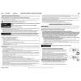
Remove the two slotted screws by using a slotted screwdriver. Remove the access cover to change the DIP switch settings. (Refer to the following figure for details changing the DIP switch settings.) After changing the DIP switch settings, replace access cover and tighten the two slotted screws using a slotted screwdriver. CAUTION Before removing the access cover to change DIP switch settings on the drive, turn off the computer and disconnect the power cord from the unit. Once the DIP switch settings have been changed, replace the access cover using the two original slotted screws provided.
Access Cover
Slotted Screws DIP Switch Figure 2-2. DIP Switch Access
12
Part 2. Preparation
|
|
|
> |
|