|
|
|
Categories
|
|
Information
|
|
Featured Product
|
|
|
 |
|
|
There are currently no product reviews.
 ;
The purchased manual is an high quality scan of the original Philips paper-based Service Manual. I am very satisfied!
 ;
The purchased manual is an scan of the original Panasonic paper-based Service Manual. Unfortunately the contrast is not perfect, but I am satisfied anyway!
;
The purchased manual is an high-quality scan of the original JVC paper-based Service Manual. The Service Manual includes the Owner´s Manual, so you do not have to buy both of them.
;
It paid to find this Service Manual, couldn't find it anywhere else. Exactly what I wanted. Received within 24 hours.
;
Complete manual with clear schematic diagrams and printed circuit board layouts of two variants of the headset and the transmitter an old and a new version.
Also shows how the headset and the transmitter is opened and how transmitter and receivers can be adjusted and where to measure.
I had no problems to repair the headset using this service manual.
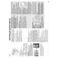
GV 31�, GV 51�, GV 61�
Drive Mechanism
Fig. 13
B456 B500
Q
B458 B464
J KI L
Fig. 17
B488
K200 K221
B484
EGHF R
R
B468 K340 K330 B478
3.16 Threading roller unit � Release the locking lug P (Fig. 11) then remove the loading drive gear (B484, Fig. 2). � Slide the threading roller units (G420 / G450, Fig. 18) in the "Thread" position then remove the threading arms (B500 / B488). � Remove the left reel brake (point 3.10). � Slide the right threading roller unit (G450, Fig. 19) in threading direction then remove it. � Remove the back tension arm (point 3.11). � Slide the left threading roller unit (G420, Fig. 19) in unthreading direction then remove it. Reassembly is carried out in reverse order. Note on reassembly: � Insert the threading arms so that the holes M / N (Fig. 18) face each other in the "Thread" drive mechanism position. � Insert the loading drive gear (B484, Fig. 13) in the "Unthread" drive mechanism position so that the hole I and the mark J on the threading arm face each other as shown in Fig. 13, and the mark L on the control slide (B464) is visible through the hole K. Press the control slide against the guides R then lock in the loading drive gear (B484).
G450 G420
X
X
X
X
3.14 Idler wheel � Remove the reel brakes (point 3.9 / 3.10). � Slide the idler wheel (K182, Fig. 14) towards the rear of the drive mechanism then remove it. Reassembly is carried out in reverse order.
K188
K182
K188
Fig. 14
MN
Fig. 18
B500 B488
3.15 Gear drive � Remove the idler wheel (K182) (point 3.14) � Remove the right reel. � Remove the reel belt (G542, Fig. 2). Remove the lock washer S (Fig. 15). Remove the pulley (K200, Fig. 15). Remove the control slide (point 3.13) Release the locking lugs T (Fig. 15) then remove the gear drive (K221). Reassembly is carried out in reverse order. Note on reassembly: � The slide disk of the gear drive (K221, Fig. 16) must be located in the guide U of the switching claw (K225) when reassembling. � The pulley (K200, Fig. 17) must be inserted so that the spring is located in the opening of the slide disk. S K222
K200
3.17 Full erase head � Turn the full erase head (G530, Fig. 19) counterclockwise then remove it.
� � � �
G530 G420 G450
Fig. 19
K225
T Fig. 15
K221
3-18 Tape reverse guide lever � Remove the pinch roller unit (point 3.8). � Unhook the spring G527 (Fig. 20). � Turn the tape reverse guide lever (G520, Fig. 20) in direction of the arrow "A" then remove it in direction of the arrow "B". Reassembly is carried out in reverse order.
"A" G527 G520 "B"
K221
U
35°
K225
Fig. 20
Fig. 16
GRUNDIG Service
4-9
|
|
|
> |
|