|
There are currently no product reviews.
 ;
downloaded next day , manual is very helpful , fast and easy
 ;
This Service Manual was exactly what I needed to repair my Philips TV. The purchase was convenient and I received the manual at the same day I paid for it.
;
Very pleased with the whole process. Great commication and very easy instructions to order and to download the manual.
;
It's a good manual, this one it's a scan from the original factory service manual, great quality 100% readeable. definetely it worths what I paid for.
;
A good manual! fast service and good qualityi for pdf document.
thanks!
1
2
3
4
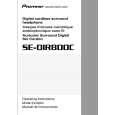
7.1.2 Disassembly 7 Transmitter
A
1. Remove the two screws of the stand. 2. Remove the four screws of the lower case. 3. Slide the cover of the upper and lower cases. 4. Remove the lower case. 5. Remove the soldering from the charge terminal. 6. Remove the three fixing screws of the phono jack. 7. Remove the Board Assy from the upper case with the VR control attached.
B
Board Assy
7 Headphones
C
<L side> 1. Remove the ear pad. 2. Remove the three screws of the base and remove the base. 3. Remove the two screws of the base cover and remove the base cover. 4. Remove the soldering from the lead wire on the photo board. 5. Remove the screw of the board.
POWER BOARD Assy
6. Remove the photo cover.
D
PHOTO BOARD Assy
<R side> 1. Remove the ear pad. 2. Remove the three screws of the base and remove the base. 3. Remove the two screws of the base cover and remove the base cover. 4. Remove the soldering from the lead wire on the photo board. 5. Remove the screw of the board.
E
MAIN BOARD Assy
6. Remove the photo cover.
PHOTO BOARD Assy
F
32
1 2
SE-DIR800C
3 4
|