|
|
|
Categories
|
|
Information
|
|
Featured Product
|
|
|
 |
|
|
There are currently no product reviews.
 ;
Perfect source for service manuals: fast and professional transaction; high quality, perfect readable and largely scaleable PDF; complete schemes, diagrams and spare part list. Tnx a lot, cu again!!!!
;
I got your link from a friend and I must say that I am really satisfied with your service. Specially this B&O manual I didn't find anywhere on the web... but you could deliver it :-) . You deliver very fast and the copy is of good quality. So your webpage is bookmarked. Thanks
;
This was the Sony CCU-500A Service manual I was looking for.
The price was reasonable.
The permission to download was quck.
I will use Owner-Manual.com for all my manual needs.
;
Excellent printing quality.
A complete and very usefull service manual with all details.
GREAT SERVICE AT VERY LOW PRICE!
A+++++++++++++++++++++++++
;
Excellent printing quality.
A complete and very usefull service manual with all details.
GREAT SERVICE AT VERY LOW PRICE!
A+++++++++++++++++++++++++
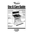
3.1.3 G3 TRANSMISSION
The CIS picks up one line of image 1728 pels. The signal is then sent to the SDIP for digital processing. This processed data is paralleled out on the data bus and dumped into the T.4 to file buffer (MMR). After the data stored to T.4 to file buffer encodes, it is transfer to file to T.4 buffer (MR, MH, MMR) for transmission. The NS32FX200 generates a vector interrupt to the CPU to tell it to be ready for transmitting the image data. The NS32FX200 outputs the serial bit stream at sigma delta oversampling rate to the analog transmitter of the AFE. The serial bit stream is fed to a 7 bit D/A converter. This D/A converter is implemented by an analog switch, which selects either + 5V or -5V inputs. These voltages are filtered by an RC low pass filter to filter supply noise. The D/A output is filtered by three pole LPF with unit gain to attenuate the out-of-band quantization noise. The output of the LPF passes to the transformer through a 3 dB gain amplifier.
Transmission Block Diagram
3-3
|
|
|
> |
|