|
|
|
Categories
|
|
Information
|
|
Featured Product
|
|
|
 |
|
|
There are currently no product reviews.
 ;
Good quality for the scan, complete, but as usual for Tascam, not so comprehensive !
 ;
great manual readable & easy to downlaod to be recommanded
;
Very useful, not the best scan, but definitely readable !
;
Complete service manual, good quality scan, great buy !
;
Excellent manual, exactly what I needed! Fair price!
.... �~-��-��
..1.:
I A
SF�7320 SF-7370
Move the No.~ mirrorbase unitto the center of the machine and secure the frontframe side takeup pulleyon the pulley shaft. Take~ pulfey \ 1 �*7pu��yskR
@ Place the tekeup pulley in the dent of me optical base as illustrat~ below and insertthe takeup pulleyshaft. NOTE: The side of the shaft with the stop pin hole must be on the rear frame side. (Frontframe stie) \
(Rear frame Stie) /.
/
NOTE:
Do not damage the wire when fasteningthe setscrew.
Move the No.Z3 mirrorbase unituntilthe frontframe side and the rear frame side contactthe stopperat the same time. @ Installthe E-ring, stop pin, and H32T (SF-7370)/CW8T (SF-7320) gea on the tekeup pulley shaft. @ Move the No.~ mirrorbase unittowardsthe paper exit side. @ Route the mirrorbase drive wire as follows.. s Set the wire end with the tension spring at@ and route it@ thru @. The spring must be hooked on the frame from underneathas shown.
q
Tighten one rear frame side tskeuDDullevsetscrewto secure it on the shaft. Move away the No.a3 rni~orbase fromthe stopperand moveit backagain to seethat it makescontactwiththe stopperat the same time the frontframe side.
~ mirrorbase
/ / 5% / R� �b
-
Tekeup pulby stopper
Route the other end of the wire in orderof~
thru~.
\.
$Sr�
I
@ Removefhe tape uaed in step (3) to holdthe wire.
q
@ If (11) above was not satisfacto~, loosenthe setscrewon the rear frame side and repeat steps (10) and (11) untilthe both side make mntact at the same time. @ Fasten another setscrewin the rear side takeup pulley.
Rotate the mirrorbase tension wire adjustingscrew clockwise to apply tension to the wire. Stop it when the edge of the wire tension springcomes in contactwithframe stopper.
Frameet-r
.
.
Rear frame�
. ? m.
Tskeup puhy
�Push tore= frame S* J L
Tekeup pUkY sh~
FW++y.Wire tenskn adjustingscrew Replacing
q
I
132+Oi+mm
i
the copy lamp leads
Remove the t~le glass. Manually move the No.23 mirrorbase unit to assure that the mirrorbase wire springend makes contactwiththe frame stop per. If not r-adjust with the adjusting screw. Insure that no wires crosseach other on the mirrorbase pulley. Remove the COPY lamp pulleyangle B fromthe copy lamp pulley angle A, and remove the copy lamp pulley angle B from the copy lamp harness.
6-7 . . . . .. -. .. ,.
 $4.99 SF7320 SHARP
Owner's Manual Complete owner's manual in digital format. The manual will be available for download as PDF file aft… 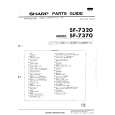 $4.99 SF-7320 SHARP
Parts Catalog Parts Catalog only. It's available in PDF format. Useful, if Your equipment is broken and You need t…
|
|
|
> |
|