|
|
|
Categories
|
|
Information
|
|
Featured Product
|
|
|
 |
|
|
There are currently no product reviews.
 ;
The manual was exactly what I needed, Good quality scans too. superb.
;
I am so happy found this site as it consists of so many Manuls and easy to aquire. This onei s exactly what I wanted and much more as it has info on not only how to use the tuner but how to repair it as well. I will come here 1st before purchasing else where! Thanks owner-manual.com!
;
Top class product, I printed it out on A3 paper and it is clear and very easy to follow.
Cheaper than buying a new radio!
;
is part of the manual is very useful for repairing
Here are circuit diagrams
if there is damage, I recommend using this part of the
a complete list of circuit boards and components
 ;
Hello.
This paper enable me, to bring this lovley Scope into Function.
Without this Page, i have no cance to make this finish.
Hans M. Knoll Germany
SF-nOo SF-n50
@ Remove the two sensor PWB holding screws from the paper ent~ side and remove the PWB as shown in the figure. ~ Move the paper stop roller shaft towardsthe rear frame side (amwhaad A) and move the shaft throughthe hole on the front frame side. Remove tie shaft from the paper exit side. (arrow head B�to C).
/3
�\
/~ /
%
\ /
~:%~.
J�� / /.�
,/,; //
�:\.A<� <
#,
9
*1.
F �v
�
Remove thePWBholdiWWrews andIifftherearframesidePWB to remove fromtheframe k
PS dufch
~R�ear frameside)
>Jgmoving the lower cassettepaper size detect .7 Remove the rear panel and right side panel R, �in reference to
A~-@. Remove the optical unit supporterand close the optical unit. Push UDthe clam shell oDen lever and open the frames. Remove the paper feed ;oller L, in referencefo D@-@. Cut the lower cassette paper empty switchlead smring wiring tie at two locationsand remove another wiringtie on the paper feed reinforcingplate. Unfasten the lead wire connector. /
@ Remove the f~r screws that ~re her paper guide and remove it.
K. Removingthe lower paperstop roller @Push up the clam shell open lever and open the frames.
..
the paper stopper front,
? T,
;. /
PS front, ier papergutie t
,
..�
Wringtie ~nng
posti anddirdn
-� ,. \ ��
@ Turn aver the paper stop front, lower paper guide and remove the two paper stop lower springs.Removethe paper stop roller shaft. PS fowar ~ng s
<; Remove the WO sensor PWB holding ~rews from the paper entrysideand removethe pWB inthe me manneras re~Ving the uppercassefiepaper Size dete~ p~ as showninthefigure. J. Removing the upper paperstop roller �.Remove the rear panei and right side panel R, in referenCeto A.�Q-~ .-,.RemovEthe optical unit s�up~tier and close the opticalUnit.. ~ push up the clam shell own. lever and open the frameS. I Removethe Paner Stw roller E-rina on the rear frame side and removethe paper stop clutch. �*OrE: ne paperstopclutchis held by a pin, it has to be replaced when re-assembling. �� aemove two E-rings on the rear frame side of the ps roller, �~shlng.frontframe side E-ring, and the bushing.
@
Mte thedirtin
oftheD%ur men mounting
NOTE: The D~ut portion of the shaft must face in the direction shown in the figure, when insating the lower paper stop roller. 0-0
�
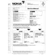
 $4.99 SF7700 SHARP
Owner's Manual Complete owner's manual in digital format. The manual will be available for download as PDF file aft… 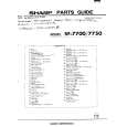 $4.99 SF-7700 SHARP
Parts Catalog Parts Catalog only. It's available in PDF format. Useful, if Your equipment is broken and You need t…
|
|
|
> |
|