|
There are currently no product reviews.
 ;
complete wiring diagram, without the part list. high quality copy. thanks for promptly.
;
Well done scan of a useful manual. It will be useful in my workbench!!
 ;
Excelent scan job. It's a fully detailed service manual of this model.
;
Do a quick order, scan quality is high.
I recommend to all!
;
This manual is perfect! Just what I needed. Thanks!
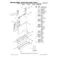
Power supply circuit
1) Power supply circuit for CPU, GATE ARRAY and RAMs.
When the main batteries are set, the voltage (9V) is applied to the terminal VDD1 of CPU (LSI1), GATE ARRAY (LSI2) and RAM (LSI4). When IC2 receives the voltage, it provides 4V to the GND lines from the terminal OUT (Pin No.1).
2)
Main switch
The CPU (LSI1) detects the informations of the Main switch by the terminal SW (Pin No.36) from the SWO signal of the GATE ARRAY (LSI2).
3)
How to turn the display ON.
When pressing "ON" key under the ON side of the Main switch , the CPU (LSI1) generates the signal to turn the display ON on the terminal V2ON (Pin No.45). This signal goes to the terminal VIN (Pin No.24) of the GATE ARRAY (LSI2), then the GATE ARRAY (LSI2) generates "L" level on the terminal VOB (Pin No.28). When the transistor 2SA1179 (Q2) receives "L" level, the transistor 2SC2812 (Q1) will be also turned ON. Then LCD drive voltage V1~V4 will be applied.
4)
How to detect the voltage for the main batteries.
When the voltage of the VDD lines becomes +6.6V±0.18V, the terminal OUT (Pin No.1) of the detector RH5V60BA (IC4) becomes "L" level, then this signal goes to the terminal INTO (Pin No.70) of the CPU (LSI1) and the terminal PDN (Pin No.35) of the GATE ARRAY (LSI2). The CPU detects the low battery condition, then the display turns OFF.
� 10 �
 $4.99 SF7900 CASIO
Owner's Manual Complete owner's manual in digital format. The manual will be available for download as PDF file aft…
|