|
|
|
Categories
|
|
Information
|
|
Featured Product
|
|
|
 |
|
|
There are currently no product reviews.
 ;
The manual is an excellent reproduction with complete schematics, made troubleshooting and repair a simple process.
;
Up to now you are the BEST! Prompt-efficient and so reasonable ! I have been after SONY service manual for quite some time !Thank you very much ! I can recomend your service to
all my collegagues ! V.Bergfield .
;
This is a very good quality print (scan) of the original SONY service manual. The original from Sony is on very thin paper. Nevertheless it is very clear and sharp and excellent readable. I'm very satisfied to have now this rare document. I've looking for it many years (infrequent). It contains very detailed circuit diagrams, exploded views, part lists, PCB view with good readable connection lines. Very recommended.
;
A complete manual with all the needed details of calibrations and service instructions about the radio receiver.
A big deal.
Many thanks !
;
Fast delivery and good quality copy. To be recommended
�
If the mode is to be set in combination with other options, use the table shown below to add up the total of the setting values for all the peripheral devices to be set, and set that total value. For example, if the SF-A56 and sorter are to be set, the total setting value is 1 + 10 = 11. Operate the keys as follows:
The leading edge position can be adjusted within a range of 8 mm (8 steps) on the stopper side and 7 mm (7 steps) on the glass side in 1 mm increments. Adjustment can be done separately for the one-sided, two-sided, and thin paper modes.
8
/
0 0
0
1
2
3
8 mm
4
5
6
9
0/ 00 01 02 03 04
6 mm
SF-A17 SF-A56
1 1
Stand/paper drawer
4
Sorter Staple sorter
10 10
Stopper
Glass
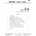
8. Adjust the center of the copy.
Set an original in the ADF tray and make a copy. When the copy is off center as shown in Fig. 1 or Fig. 2, loosen the two tray securing screws and adjust the tray by moving it in direction A orB as shown in the figure.
V iew from the operator side
Setup example
(1) If the leading edge of the original was not fed all the way to the stopper, enter value which will move the original toward the stopper side. 7, 6, 5, 4...
Original
Mark
Tray securing screw
B
A
Stopper
Glass
(2)
If the copy image at the leading edge was distorted, enter value which will move the original toward the glass side. 9, 10, 11...
Original Stopper
Glass
5 When off center as shown in fig. 1 Move the tray in direction A and secure it with the two mounting screws. Make a copy to check whether it is centered properly.
Fig. 1 Center of copy paper
Stopper
(3)
If the original overrode the stopper, enter value which will move the original toward the glass side. 9, 10, 11, 12 ...
Original
Glass
�
Center of original image (first copy)
After selecting test command 53 , enter a selected set value between 0 and 15 using the copier keys.
C
5 When off center as shown in fig. 2 Move the tray in direction B and secure it with the two mounting screws. Make a copy to check whether it is centered properly.
Fig. 2 Center of copy paper
0/
4
2
(a)
0/
0
(b)
1
(a) One-sided mode (b) Two-sided mode (c) One-sided thin paper mode *For SF-A17, only (a) and (c) are possible.
(c)
2
Center of original image (first copy)
9. Adjust the position of the leading edge of originals
� �
The position of the leading edge of originals fed from the ADF can be determined using test command 53 . Although the leading edge has been factory set to stop at location (8), it may need to be adjusted depending on the type of originals. �4�
Set to between 0 and 15 as dictated by the copier's performance. The factory setting is "8".
 $4.99 SF-A56 SHARP
Parts Catalog Parts Catalog only. It's available in PDF format. Useful, if Your equipment is broken and You need t…
|
|
|
> |
|