|
There are currently no product reviews.
 ;
A good manual! fast service and good qualityi for pdf document.
thanks!
 ;
Very helpful and complete manual. Maybe only one negative is schematics have sometimes unreadable name of the parts. But it's not a big problem.
;
Excellent high quality schematics brought my old Heidelberg back to life. Fast download at a reasonable price. Thanks.
;
This document is just what I was looking for, it´s very useful, it contains adjustment procedures for the final stage of the power amp and also
has a complete wiring diagram and description of the main semiconductors used in the design.
;
Dear Sirs,
Thank you for the fast support, the manual does provide all necessary information to repair the radio. All schematics are in a good quality for reading.
The manual fits 100% to my requirements as a technican.
Kind regards Thomas
Front
Surround
Subwoofer
Center
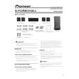
RRV3754
S-FCRW3100-K
ORDER NO.
SPEAKER SYSTEM
S-FCRW3100-K
XTWUC
1. REASSEMBLY AND DISASSEMBLY PRECAUTIONS
1.1 FRONT/SURROUND SPEAKER 1.2 CENTER SPEAKER
The grille is attached to the cabinet by 4 external screws. To detach it, unfasten those screws. The speaker unit, together with the grille, is attached to the cabinet by 4 external screws. To detach it, first unfasten those screws. Next remove the cabinet. Then remove the cable. When attaching it, face its terminal downward. The grille assy is attached to the cabinet by 8 external screws. To detach it, unfasten those screws. The speaker unit, together with the grille assy, is attached to the cabinet by 4 external screws. To detach it, first remove the grille assy. Next remove the cabinet. Then remove the cable. When attaching it, face its terminal toward the input terminal. The speaker unit is attached to the bottom by 4 external screws. To detach it, unfasten those screws. When attaching it, face its terminal backward. The cosmetic baffle assy is attached to the baffle board by press-fitting. To detach it, pry it open by inserting a flat blade screwdriver into lower slot.
1.3 SUBWOOFER
4-1, Meguro 1-chome, Meguro-ku, Tokyo 153-8654, Japan PIONEER ELECTRONICS (USA) INC. P.O. Box 1760, Long Beach, CA 90801-1760, U.S.A. PIONEER EUROPE NV Haven 1087, Keetberglaan 1, 9120 Melsele, Belgium PIONEER ELECTRONICS ASIACENTRE PTE. LTD. 253 Alexandra Road, #04-01, Singapore 159936
PIONEER CORPORATION
PIONEER CORPORATION 2008
T-ZZR APR. 2008 Printed in Japan
|