|
|
|
Categories
|
|
Information
|
|
Featured Product
|
|
|
 |
|
|
There are currently no product reviews.
 ;
Veramente completo, dettagliato e perfetto nella visione. Perfect, thanks!
 ;
Fully functional usable service manual. Considering the age of the manual and device quality was better than expected
;
Thank you very much, I've been very happy to find this manual on "Owner Manual". It's a perfect copy and it has been really useful for my work!
;
It took about 24-hours after my payment before I was able to get to the download. Apparently, payment processing is not 100% automated. That is no big deal, just be aware of that going in.
After I got to it, it was in good shape, easy to read, etc. Not some cheap FAX copy looking thing.
Also, this site was the cheapest I found. Another Plus!
;
Good price, very legible manual, exactly what I needed -- but had to wait a day to actually get the download of the manual. Would have preferred to download it immediately after payment rather than waiting for someone to "process" my order. I was surprised that I had to wait that long.
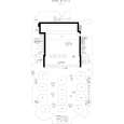
2 . SGH - D 5 0 0
C ir c u it
D e s c r ip t io n
1. SGH-D500 RF Circuit Description
1) RX PART
1. ANTENNA SWITCH (U100 SWICHPLEXER) ¡æ Switching Tx, Rx path for GSM900, DCS1800 and PCS1900 by logic controlling. 2. ANTENNA SWITCH Control Losic (U100) ¡æ Truth Table VC1 Tx Mode (GSM900) Tx Mode (DCS1800/1900) Rx Mode (GSM900) Rx Mode (DCS1800) Rx Mode (PCS1900) L L(H) L L H VC2 H L L L L VC3 L H L L L
3. FILTER To convert Electromagnetic Field Wave to Acoustic Wave and then pass the specific frequency band. - GSM FILTER (F100) ¡æ For filtering the frequency band between 925 and 960 MHz - DCS FILTER (F102) ¡æ For filtering the frequency band between 1805 and 1880 MHz. - PCS FILTER (F101) ¡æ For filtering the frequency band between 1930 and 1990 MHz. 4. VC-TCXO (U101) This module generates the 26MHz reference clock to drive the logic and RF. It is turned on when the supply voltage Vcc(SYN) is applied. After buffering a reference clock of 26MHz is supplied to the other parts of the system through the transceiver pin CLKOUT. 5. TRANSCEIVER (U102) This chip is fully integrated GSM GPRS quad-band transceiver with transmit baluns, loop filters and most of the passive component in it. And also fully integrated fractional N RF synthesizer with AFC control possibility, RF VCO with integrated supply regulator. Semi integrated reference oscillator with integrated supply regulator. RF Receiver front-end amplifies the E-GSM900, DCS1800 and PCS1900 aerial signal, convert the chosen channel down to a low IF of 100kHz. In IF section, further amplifies the wanted channel output level to the desired value and rejects DC.
2) TX PART
The transmitter is fully differential using a direct up conversion architecture. It consists of a signal side band power up mixer. Gain is controlled by 6 dB via 3-wire serial bus programing. The fully integrated VCO and power mixer achieve LO suppression, quadrature phase error, quadrature amplitude balance and low noise floor specification. Output matching/balun components drive a standard 50 ohms single ended load.
2- 1 SAMSUNG Proprietary-Contents may change without notice This Document can not be used without Samsung's authorization
|
|
|
> |
|