|
|
|
Categories
|
|
Information
|
|
Featured Product
|
|
|
 |
|
|
There are currently no product reviews.
 ;
The content of the manual was not found on the Internet and was a hard find. I check the net for 5 hours until I came across this web-site. When I did find the book it Auto loaded into my IPAD PDF shelf for books for review at anytime. Overall I am satisfied with the book and it answered all my questions. This repair book is obsolete because the product I bout it for is pretty old. Thanks for the help with the download and even having the manual. Thanks 73's K5HRD
;
Excellent manual including schematics. The service was great and the manual helped complete the job.
;
It was magic after so many years to still be able to source this info. It was equally amazing to return my Pioneer receiver to it near new sound quality AFTER NEARLY 30 YEARS! Thank you for this ability!
;
Very quick and easy website to use and fast download of manual, quality of manual is excellent and will be pleased to use this service again in the future, thanks so much!
 ;
Easy and secure way to get a complete service manual of a vintage hifi component. Only some parts of the print copy are dificult to read. Nice price!
SJ-58L-T2 SJ-63L-T2 SJ-68L-T2
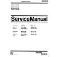
2 Replacing Handles and Door Parts
1. Remove Screw caps and Screws on each door handle, then remove the handles. Flatten the surface of the screw holes using the handle of a screwdriver, etc., then mount 3 units of F (Door hole covers) on each door. 2. Remove the Nylon bearings, Door stopper(Lower door only), Stopper springs on the right side of each door and the cap on the left side of the Upper door. Furthermore, open the hidden holes on the bottom of the door using a screwdriver, then remove a screw (Lower door only). 3. Remove Screw caps and Screws on the right side of each door, then remove the Door cap covers and mount D and E (Door cap covers) on the left side. 4. Replace Nylon bearings to the left side of each door, then mount the Upper door cap on the right side. Furthermore, mount Door stopper and B and C(Stopper springs) on the left side as well. Screw in a screw in the screw hole on the lower right of the Lower door. 5. Fix upper portion of Upper handle using one screw on the right side of Lower door, then temporarily fix the handle to the door using tape. 6. To open screw holes, first make marks on the doorplate surface through the 3 holes of the handle, then temporarily remove the handle (make sure that the dimensions of the markings are as shown in the diagram). 7. Lightly dent the center of each marking, then open holes using a 3.8 mm drill bit. Use a drill guide, etc., to prevent the drill bit from entering more than 5 mm. Make sure to open the hole straight. Opening the hole in an angle will cause the handle to clatter. The door will be unusable if the hole are too large or too deep or if the screws are tightened too much. 8. Mount the handle using the 4 screws and install Screw caps. 9. Mount Lower handle on the right side of Upper door by repeating steps 5. ~ 8. above.
2
F
12
4
2
5,6
16mm 27mm
3 1 3 4 4
172mm 172mm
D B
2 3
2
7
E
3 11
5mm
8
(J) F
2 4 2 4 2
5-8 9
C
Figure M-2
22
|
|
|
> |
|